
Summary of Contents for Chainway UR4
- Page 1 SHENZHEN CHAINWAY INFORMATION TECHNOLOGY CO., LTD Fixed UHF Reader UR4 User Manual...
-
Page 2: Statement
(licensed program). Except as noted below, such license may not be assigned, sublicensed, or otherwise transferred by the user without prior written consent of Chainway. No right to copy a licensed program in whole or in part is granted, except as permitted under copyright law. -
Page 3: Table Of Contents
Statement ..................1 Chapter 1 Product Intro ..............3 Intro ..................3 Brief ..................4 Device List ................5 Device installation ..............6 GPIO ................... 6 Chapter 2 Installation instructions ............. 7 2.1 Appearance ................7 2.2 Parameter Setup ..............8 Chapter 3 Read and Write EPC ............ -
Page 4: Chapter 1 Product Intro
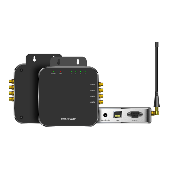
Chapter 1 Product Intro 1.1 Intro Chainway UR4 is a high-performance four-channel fixed UHF reader. The core chip adopts Impinj R2000 module with high integration and excellent performance. With Stable and reliable capacity, excellent anti-electromagnetic interference capability and heat dissipation... -
Page 5: Brief
1.2 Brief UR4 has adopted DC 12V/5A power supply, it can be equipped with multiple types of antennas with different output power such as 6dBi, 9dBi and 12dBi. Also UR4 has adopted SMA female port, RS232 and RJ45 interfaces, Windows SDK and demo are provided. -
Page 6: Device List
1.3 Device List 1. UR4 fixed reader, 12V/5A power adaptor. 2. UHF antennas: 6dBi, 9dBi, 12dBi etc. 3. Feeder line that has adopted with SMA male port, the port on other side needs to be equipped with antenna. 4. RJ45 Ethernet cable. -
Page 7: Device Installation
Ethernet cable through RJ45 port. (Default IP address of UR4 is 192.168.99.202, Port is 8888). PC needs to be set with UR4 in same network segment and PC could connect with multiple UR4 devices through switchboard or similar. -
Page 8: Chapter 2 Installation Instructions
2、IO3-4:Controllable by software, maximum switching voltage of electric relay is 220Vdc,250Vac; 3、IO5:Optically coupled 1 input LED+, voltage range between IO5 and IO6 is 3-5.5V, maximum current is 50mA; 4、IO6:Optically coupled 1 input LED-, voltage range between IO5 and IO6 is 3- 5.5V, maximum current is 50mA;... -
Page 9: Parameter Setup
2.2 Parameter Setup Double click UHFAPP.exe to enter software, and connect with device through serial port line. Select Mode to “SerialPort”, select COM to according serial port on PC. Click “Open” to connect with device, initiation page is as follows: If RJ45 has been used as connection, communication Mode needs to be selected as “network”... - Page 11 After device has connected with PC, the parameters on interface will be empty. Click “Get” on each option to collect device parameters. Click “Set” on the page, user can adjust necessary parameters, some parameters are default values. Output power can be set in range of 5 dBm to 30 dBm as following picture, after select value, click “Set”...
- Page 12 Set RFLink: Set continuous wave: There are two work modes can be selected, “command mode” and “auto mode”. Under “command mode”, user could collect tag data in “Read EPC” page, click “Start” to send command to device on PC, click “Stop” to stop collecting tag data.
- Page 13 Set IP address and make sure PC and device have used in same segment. For example, if IP address of PC is 192.168.1.109, mask is 255.255.255.0, the device IP address can be set to 192.168.1.201, port number doesn’t need to be changed. Set antenna connection, there are 4 I/O ports on device and have been marked as ANT1, ANT2, ANT3, ANT4.
- Page 14 Set FastID: Set TagFocus: Set protective temp. It means to setup highest operating temperature of UHF module: Set EPC and TID:...
- Page 15 Reset, click “Reset” button to restore device to default value. After reset, user needs to click “Close” and “Open” to reconnect the device. Set Buzzer, click “Open” to switch on buzzer function, device will play notification sound when reading tags. Set Gen2, this parameter needs to be adjusted by actual requirements.
-
Page 16: Chapter 3 Read And Write Epc
Chapter 3 Read and Write EPC 3.1 Read EPC Click “ReadEPC” in menu to enter EPC page, click “Start” to read tags, click “Stop” to stop reading. The EPC, RSSI, Count number and ANT number (antenna channel) will be recorded in window as following pic: User could enter data in “Filter”... -
Page 17: Read & Write Tags
3.2 Read & Write Tags Click “ReadWriteTag” to enter its page, TID area can be read only, RESERVED, EPC and USER areas can be read and written. - Page 18 Click one option in “Read-write” window to enter tag reading mode, EPC will be automatically copied into “Data” block in filter, default option is EPC reading, click “Read” to read 12 bytes of EPC area.
- Page 19 For “RESERVED” area, user could read 4 words at maximum, previous 2 words are password of KILL function, last 2 words are access passwords: Read TID area:...
- Page 20 Read USER area: Data could be written in EPC, RESERVED and USER areas, select according areas and input initial address, length, input data into “Data” window and click “Write” to write data into according areas.
-
Page 21: Lock Uhf Tag
3.3 Lock UHF Tag Click “Kill-Lock” in main menu to enter Tag locking function. For this function, user could execute “Lock”, “Kill”, “Open”, “Permanent Open” and “Permanent Lock”, to execute “Lock” function, password is needed. If user wants to kill UHF tag, need to enter password and tag will be wasted permanently. -
Page 22: Udp-Receiveepc
3.4 UDP-ReceiveEPC After auto mode has been selected, restart device and select UDP- ReceiveEPC, click “Open” to connect device and select IP address of PC in address column, click “Stop” to stop receiving UHF tag data. If user needs to escape auto work mode, “command mode” needs to be selected in work mode. -
Page 23: Others
3.5 Others Click “UHF information” in main menu to read hardware version and firmware version, click “Temperature” to read current temperature value of UHF module.
Need help?
Do you have a question about the UR4 and is the answer not in the manual?
Questions and answers