Advertisement
Quick Links
READ CAREFULLY BEFORE ATTEMPTING TO ASSEMBLE, INSTALL, OPERATE OR MAINTAIN THE PRODUCT
DESCRIBED. PROTECT YOURSELF AND OTHERS BY OBSERVING ALL SAFETY INFORMATION. FAILURE
TO COMPLY WITH INSTRUCTIONS COULD RESULT IN PERSONAL INJURY AND/OR PROPERTY DAMAGE!
RETAIN INSTRUCTIONS FOR FUTURE REFERENCE.
WARNING!
MODELS 4F649, 4F650 AND 4F651 ARE INTENDED
TO BE USED AS BI-ROTATIONAL PUMPS ONLY. THE
REMAINING MODELS CAN BE USED AS BI-ROTATIONAL
PUMPS AND/OR FLUID MOTORS.
650
651
649
652
X
X
X
X
PUMPS
FLUID
N/A N/A N/A
X
MOTORS
Description
Our hydraulic pumps/fluid motors are highly efficient
and specifically designed for bi-directional rotation. They
utilize an external gear fixed displacement design and are
of a durable cast iron construction. They incorporate an
internally lubricated ball bearing on the drive shaft which
will withstand up to 150 lb. side load.
They can be used for direct drive or for belt driven appli-
cations. As hydraulic pumps they are suitable for use in a
wide variety of material handling, agricultural, and con-
struction equipment applications; in addition to machine
tools, robotics, and other types of machinery. As fluid
motors, typical examples of applications are hose reel
drives, index tables, conveyor drives, lawn mowers and
many other applications where rotary motion is required.
Unpacking
Due to cast iron construction, very little damage can
occur during transit. Do not remove the plastic shipping
plugs from the ports until ready for installation. This will
keep dirt or foreign material from entering the system.
Check carton for the following loose components: (1)
pump/fluid motor assembly, (1) 4-bolt mounting gasket,
(4) 5/16-18" UNC x 3/4" mounting bolts with lockwashers,
and (1) square drive key should be taped to drive shaft.
If any of these components are missing or there is any
noticeable damage, please contact the office where item
was purchased.
Specifications
Cast iron hydraulic pump/fluid motor, bi-rotational,
4-bolt 4F17 mounting, 11 tooth gears, 1.50" shaft exten-
sion, 0.50" shaft diameter with 0.125" square x 1" drive
key, 400 PSI shaft seal, side porting with SAE straight
thread ports, internally lubricated ball bearing for side
loads to 150 lbs.
653
654
655
656
657
658
X
X
X
X
X
X
X
X
X
X
X
X
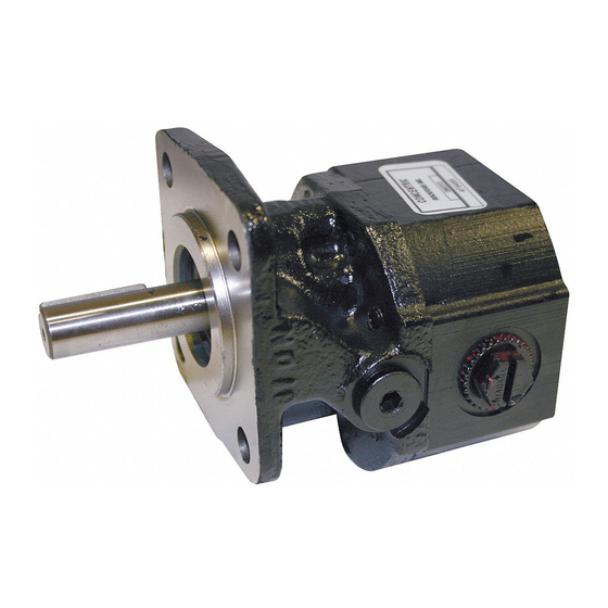
OPERATING INSTRUCTIONS & PARTS MANUAL
HYDRAULIC GEAR PUMPS
MODELS 4F649 THRU 4F659
Figure 1
659
X
X
3.28
1.38
1.500
3.000
3.25
"B" SAE PORT
2.812
1.41
1.000
CASE DRAIN
2.000
Figure 2 - Dimensions
PUMP/FLUID MOTOR DIMENSIONAL DATA
MODEL
4F649
4F650
4F651
4F652
4F653
4F654
4F655
4F656
4F657
4F658
4F659
Concentric P/N 2690098
Revised 02/06/2012
2.76
.500
.125
A
1.500
.344 DIA. MTG. HOLD
(4) PLACES
HYDRAULIC SCHEMATIC
2.000
2.82
1.000
1.41
BI-ROTATIONAL
GEAR PUMP
DIMENSIONS
A
3.16"
3.16"
3.16"
3.16"
3.69"
3.69"
3.69"
3.69"
3.69"
4.20"
4.20"
.28
1.00
1/8" SQ. KEY
1.7815
.5000
BI-ROTATIONAL
HYDRAULIC
MOTOR
B
9/16-18
9/16-18
3/4-16
3/4-16
3/4-16
7/8-14
7/8-14
7/8-14
7/8-14
7/8-14
7/8-14
Advertisement

Subscribe to Our Youtube Channel
Related Manuals for Concentric 4F649

Summary of Contents for Concentric 4F649
- Page 1 TO COMPLY WITH INSTRUCTIONS COULD RESULT IN PERSONAL INJURY AND/OR PROPERTY DAMAGE! RETAIN INSTRUCTIONS FOR FUTURE REFERENCE. WARNING! MODELS 4F649, 4F650 AND 4F651 ARE INTENDED TO BE USED AS BI-ROTATIONAL PUMPS ONLY. THE REMAINING MODELS CAN BE USED AS BI-ROTATIONAL PUMPS AND/OR FLUID MOTORS.
-
Page 2: Installation
Assembly 14. When using the assembly as a pump keep inlet hose Models 4F649 through 4F659 are packaged fully assem- short and of adequate size to avoid pump cavitation. bled and require no further assembly. - Page 3 2690098 MODEL 4F649 THRU 4F659 OUR FLUID MOTOR SPECIFICATIONS PUMP/FLUID MOTOR DIMENSIONAL DATA DIMENSIONS MAX. PRESSURE STOCK DISP. CONT. INTER. CU.IN./REV. MODEL 4F652 0.194 3000 3500 4F649 3.16” 9/16-18 4F650 3.16” 9/16-18 4F653 0.258 3000 3500 4F651 3.16” 3/4-16 4F654 0.323...
-
Page 4: Maintenance
2690098 MODEL 4F649 THRU 4F659 Installation (Continued) exceeding 400 PSI, then the case drain port must be utilized. The case drain feature can be used by NOTE: Be sure adequate cooling for the hydraulic oil is removing the steel 7/16-20 SAE O-ring plug (see provided. -
Page 5: Toubleshooting Chart
2690098 MODEL 4F649 THRU 4F659 Toubleshooting Chart SYMPTOM POSSIBLE CAUSE(S) CORRECTIVE ACTION Pump does not 1. System relief valve set too low, 1. Check system relief valve for proper develop full pressure or leaking setting with pressure gauge in outlet line 2. - Page 6 2690098 MODEL 4F649 THRU 4F659 ORDER REPLACEMENT PARTS BY CALLING TOLL FREE 1-800-323-0620 Please provide following information: Address parts correspondence to: • Model Number Parts Company of America • Serial Number (if any) 1657 Shermer Road • Part Description and Number Northbrook, IL 60062-5362 U.S.A.
- Page 7 2690098 MODEL 4F649 THRU 4F659 Replacement Parts List for Models 4F649 thru 4F659 PART DESCRIPTION QTY. 4F649 2350268 4F650 2350268 Drive shaft 4F651 2350266 4F652 2350266 4F653 2720319 4F654 2720320 Drive shaft 4F655 2720321 4F656 2720322 4F657 2720323 Drive shaft...
Need help?
Do you have a question about the 4F649 and is the answer not in the manual?
Questions and answers