
Summary of Contents for Bartec DTL III Ex
- Page 1 Operating manual RU C-DE.ГБ06.B.00399 Digital safety temperature limiter DTL III Ex Type 17-8865-4.22/2200 3000...
- Page 2 Reservation Technical data subject to change without notice. Changes, errors and misprints may not be used as a basis for any claims for damages. EN 2/12...
-
Page 3: Table Of Contents
Content 1. Use in accordance with the intended purpose 2. Product description 2.1. General points 2.2. Display and control elements 3. Safety instructions 4. Assembly, installation and commissioning 4.2. Installation 4.3. Commissioning 5. Basic settings of the system parameters 5.1. General points 5.2. -
Page 4: Use In Accordance With The Intended Purpose
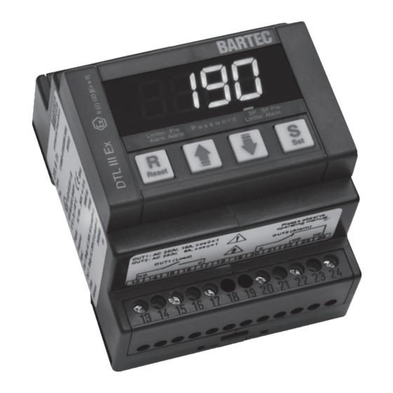
2.1. General Points Operation LED Limiter alarm Operation LED SP pre-alarm The 16 A load current circuit of the DTL III Ex is opened and interlocked as soon as the temperature Operation LED SP limiter alarm Operation LED of the resistance thermometer exceeds the heating... -
Page 5: Safety Instructions
Note: When controlling Ex heating circuits, the access password for the setpoint limit alarm and the password for resetting limiter alarms must be set, since the setting of the DTL III Ex in accordance with EN 60079-7 or EN 60079-30-1 must be “secured” and “sealed” for interaction with explosion-protected heating circuits. -
Page 6: Basic Settings Of The System Parameters
DTL III Ex Type 17-8865-4.22/2200 3000 Operating manual 5. Basic setting for the system parameters 5.1. General points If there is no key actuation for approx. 15 seconds in programming mode, the parameter level is quit automatically and the basic display appears. -
Page 7: (Incl. Limit Value) (Pas.2)
DTL III Ex Type 17-8865-4.22/2200 3000 Operating manual 6. Mode of operation of the device 6.1. Temperature limitation, pre-alarm, service entry Actual value Limiter (PV) 5.5. Setting the password for system parameters alarm (AL 1) (incl. limit value) (PAS. 2) -
Page 8: Remote Reset
- Remote reset (RESET) 9.2. TC RU - Service contact (OFF) Ex protection type The DTL III Ex contact family has a service contact Floating contacts, key switchs required Ex e II U (DIG.IN 2), which is used to deactivate the load output Contact loadability at least 5 V, 5 mA) and to block the temperature alarms, e.g. -
Page 9: Electrical Connection/Device Connections
Terminals 20, 22, 24 Floating contacts changeover contact Out2 (group fault alarm) The wiring diagram shows the connection of the DTL III Ex in conjunction with the DPC III temperature controller to monitor a heating circuit Power supply A-B see type label... -
Page 10: List Of Parameters
Measurement reading above sensor limit measurement reading. Reset the fault signal by pressing the “reset“ button. 16. Type explanation/device labelling Type 17-8865-4722/22003000 Description DTL III Ex; AC 100 to 240 V Terminal plate top Type label Terminal plate bottom ϕ... -
Page 11: Dimension Diagram
DTL III Ex Type 17-8865-4.22/2200 3000 Operating manual Typ 17-8865-4C22/22003000 Description DTL III Ex 24; AC/DC 24 V Terminal plate top Type label Terminal plate bottom ϕ OUT1: AC 250 V, 16 A, cos = 1 Please observe OUT2: AC 250 V, 8 A, cos = 1... - Page 12 BARTEC Max-Eyth-Str. 16 Tel.: +49 7931 597 0 info@bartec.de GmbH 97980 Bad Mergentheim Germany Fax: +49 7931 597 119 www.bartec.de...
Need help?
Do you have a question about the DTL III Ex and is the answer not in the manual?
Questions and answers