Table of Contents
Advertisement
Quick Links
Advertisement
Table of Contents

Related Manuals for Alamarin Jet AJ 285


Summary of Contents for Alamarin Jet AJ 285
- Page 1 Operation and maintenance manual...
-
Page 3: Table Of Contents
Table of contents Operation and maintenance manual Table of contents 1. Introduction ....................1 1.1. Safety precautions ................1 1.2. Symbols ..................... 1 2. The Jet Propulsion Unit ................3 2.1. Structure .................... 3 2.2. Serial number ..................4 3. Operation ..................... 5 3.1. -
Page 5: Introduction
Introduction Operation and maintenance manual 1. Introduction Congratulations on purchasing your new Alamarin-Jet AJ 285 water jet propulsion unit! This manual contains important information on the operation, use and maintenance of the unit. Please read these instructions carefully before using the unit. - Page 6 Introduction Operation and maintenance manual Icon Description WARNING Negligence in the performance of the procedures can lead to personal injury, breakdown of equipment, or serious malfunction of the equipment. CAUTION The procedure involves minor danger or a possibility of minor damage to equipment.
-
Page 7: The Jet Propulsion Unit
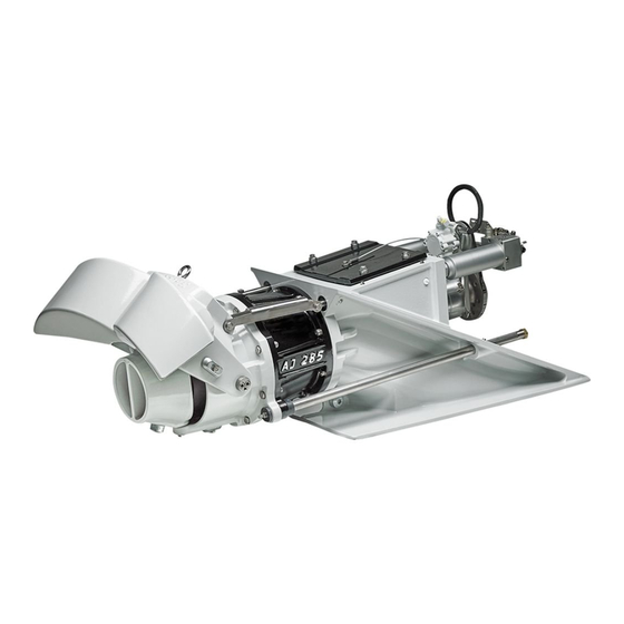
Operation and maintenance manual 2. The Jet Propulsion Unit The Alamarin-Jet water jet propulsion unit (jet) is a single stage axial flow pump, which produces a high volume flow rate and thrust with high efficiency. The operation of the unit is based on increasing the water flow rate in the nozzle. -
Page 8: Serial Number
The Jet Propulsion Unit Operation and maintenance manual Part Purpose Controlling device Causes the boat to reverse and stop. Lowering the reversing deflector causes the boat to reverse. The direction of the jet flow changes obliquely forward under the boat, which is when the thrust is directed forward and down. -
Page 9: Operation
Operation Operation and maintenance manual 3. Operation If you have never driven a jet boat before, familiarise yourself with the separate guide “Steering and controlling jet boats” before driving the boat for the first time. 3.1. Starting Before you start the engine equipped with the jet, make sure that •... -
Page 10: Steering
Alamarin-Jet Oy is not liable for damages which derive from incorrect installation of the system. Steering denotes exclusively moving the steering nozzle. Steering means changing the boat's bow angle. -
Page 11: Controlling
Operation Operation and maintenance manual Turning the nozzle from one extreme position to the other takes between 1 and 3 revolutions of the steering wheel, depending on the capacity of the steering pump used. TIP! When the boat is not in use, it is advisable to turn the wheel all the way to the left. - Page 12 Operation Operation and maintenance manual Figure 6. Ahead Throttle lever Control lever Rear position When the reversing deflector control lever is in the rear position, the deflector is blocking the jet flow and the boat moves astern (figure 7). Figure 7. Astern Throttle lever Control lever Centre position The centre position of the control lever corresponds to the ”idle”...
-
Page 13: Using The Reversing Deflector
Operation Operation and maintenance manual TIP! When the boat is not in use, it is advisable to raise the reversing deflector into the upright position. This will protect the cylinder rod and prevent it from collecting dirt, thus increasing the service life of the seals. For long-term storage, you can ensure that the reversing deflector stays in the upright position by tying it from the lifting loop to the stern of the boat. -
Page 14: Dry Running
Operation Operation and maintenance manual Figure 8. Suction power of the intake Loose objects may get sucked into the grass rake and small objects may wash through the jet. Stones may cause damage to the jet and its parts. In sandy conditions, the impeller inevitably wears. A worn impeller requires maintenance (section 4.8. -
Page 15: Maintenance
However, maintenance must be performed regularly and whenever the need arises. Alamarin-Jet can provide you with a toolkit, available through separate order, for maintenance purposes. The toolkit includes the tools needed to perform most maintenance and repair procedures on the jet. The tools included in the toolkit are specified in table 3. - Page 16 Maintenance Operation and maintenance manual The jet is protected from galvanic corrosion with passive cathodic protection, i.e. with anodes. Every critical aluminium casting has its own anode. The locations of the anodes are shown in figure 9. Figure 9. Anodes Steering nozzle (1 pc) Stator (1 pc) Reversing deflector (2 pcs) Impeller tunnel (1 pc)
-
Page 17: Touch-Up Painting And Antifouling
Maintenance Operation and maintenance manual Figure 10. Stator anode The stator is protected by an anode housed under a plastic plug located on the starboard side the stator. To remove the anode, first open the arrester screw (figure 10, point A) and unscrew the plug. Now you can replace the anode located inside the plug. -
Page 18: Bearing
Maintenance Operation and maintenance manual WARNING! Familiarise yourself with antifouling before painting the propulsion unit with antifouling paint! Painting the propulsion unit with antifouling paint that contains copper will result in heavy corrosion and destruction of the propulsion unit. Do not use any other antifouling paints for painting the propulsion unit except those intended for aluminium surfaces. -
Page 19: Lubricating The Front Bearing
Maintenance Operation and maintenance manual Figure 12. Bearing 4.3.1. Lubricating the front bearing The front bearing is oil-lubricated and the housing is secured with a mechanical sealing. When the shaft rotates, the oil circulates through the reservoir and impurities gather to the bottom of the reservoir on the drain plug magnet (figure 13, point A). -
Page 20: Lubrication Of The Rear End Bearing
Maintenance Operation and maintenance manual The front bearing oil must be changed after the first 20 hours of driving and then after every 500 hours or once every driving season. Before you start changing the oil, make sure you have a container for draining the used oil. - Page 21 Maintenance Operation and maintenance manual Figure 14. Automatic lubrication unit Oil pressure hose from the Grease nipple hydraulic cylinder Scale Grease hose to the lubrication channel Piston Feeding You can adjust the feed as follows: • If the automatic lubrication unit feeds too much grease (the reservoir empties too soon), reduce the pressure by loosening the adjusting screw (figure 15).
-
Page 22: Control System
Maintenance Operation and maintenance manual Figure 15. Lubricating the Rear Bearing The amount of grease fed to the rear bearing must be 0.1 l/100 h (6 cu in/100 h). The grease volume in the unit is 0.3 l (18 cu in). With these settings, the reservoir empties after 300 hours. -
Page 23: Seals
Maintenance Operation and maintenance manual where waterproof petroleum jelly should be added during maintenance are marked in figures 16–17. When the plastic bearings of the joints wear and gaps are created, they must be replaced. Figure 16. Steering nozzle joints Figure 17. Reversing deflector joints 4.5. Seals The only seal that needs to be checked is the inspection hatch seal (figure 18). -
Page 24: Hydraulic Reversing Deflector Control System
Maintenance Operation and maintenance manual Figure 18. Inspection hatch seal If the inspection hatch seal leaks, it will cause ventilation or water leakage in the engine room if the inspection hatch is inside the engine room (see section 5.2. , page 34). Ventilation CAUTION! If water gathers in the bilge, the cause for this must be... - Page 25 Maintenance Operation and maintenance manual In a stock delivery, the system does not include a control lever or a cable, so their type varies depending on the boat manufacturer. However, the different types of systems have the following things in common: •...
- Page 26 Maintenance Operation and maintenance manual Figure 21. Checking the oil level Maximum level Minimum level Note that the oil must be changed once every driving season. The type of oil to use is described in appendix 3. , page 41. Oil recommendations Amount of oil in the hydraulic system and the front bearing Hydraulics: 1.3–1.7 L...
- Page 27 Maintenance Operation and maintenance manual Figure 22. Oil reservoir cover screws The filter is located under the cover and has a spring on top of it that keeps the filter in place (figure 23). Figure 23. Oil filter spring 2. Remove and replace the spring and the filter. It is not necessary to replace the spring unless it is damaged.
-
Page 28: Raw Water Cooling
Maintenance Operation and maintenance manual Figure 24. Oil reservoir cover 4. Reattach the six cover screws (figure 22). 4.7. Raw water cooling Figure 20 shows a system in which the cooling water comes from the jet (section 4.7. , page 24). The system can consist of Raw water cooling different looking components depending on the boat manufacturer. -
Page 29: Checking The Impeller
Maintenance Operation and maintenance manual should be as small as possible to achieve maximum efficiency. (The factory installation gap is 0.4 mm (approx. 0.016") when the stator centres the shaft). When the gap expands too much, the jet's performance decreases. The impeller usually wears on the outer edge of the blades. - Page 30 Maintenance Operation and maintenance manual Before the impeller can be removed, the reversing deflector, the steering nozzle and the stator must be removed. Removing the impeller: 1. Open the screws indicated by arrows in figure 26. WARNING! Make sure that the reversing deflector is not accidentally lowered.
- Page 31 Maintenance Operation and maintenance manual Figure 27. Stator fastening screws There are eight screws, four of which are shown in the figure. 3. Remove the stator, reversing deflector and steering nozzle as a complete unit (figure 28). Figure 28. Removing the stator, reversing deflector and steering nozzle KHO/285/EN/1.0.0.
- Page 32 Maintenance Operation and maintenance manual The impeller is connected to the shaft either with a mounting cone or a locking plate attached to the end of the shaft. The impeller connection method depends on the model of the impeller. Instructions for removing the impeller are provided below for both connection methods.
-
Page 33: Installing The Impeller
Maintenance Operation and maintenance manual Figure 30. Impeller fastening screws, locking plate 5. Remove the impeller from the shaft together with the sleeve (figure 30, point C), and the mounting flange (figure 30, point D). 4.8.3. Installing the impeller New and repaired impellers are fitted in the same way. The impeller is connected to the shaft either with a mounting cone or a locking plate attached to the end of the shaft. - Page 34 Maintenance Operation and maintenance manual Figure 31. Position of the wedge groove The thrust caused by the impeller is transmitted through the adjuster sleeve to the shaft (figure 32, point A). The sleeve consists of rings of different thickness. The length of the sleeve can be adjusted in 0.5 mm (approx.
- Page 35 Maintenance Operation and maintenance manual 4. Place the impeller into the duct. Mounting cone: At this point the screws of the plastic mounting cone must be fingertight. 5. Measure the gap on the impeller outer race. The optimal gap is 0.8–1.2 mm (approx. 0.031–0.047") at the upper part of the duct.
-
Page 36: Intermediate Shaft
Maintenance Operation and maintenance manual 8. Install the stator and the steering nozzle in place in reverse order to that when removing (section 4.8.2. , page 25). Removing the impeller The torque to be used is the tightening torque for M10 bolts. 4.9. Intermediate shaft The intermediate shaft which is connected between the jet and the engine usually depends on the boat manufacturer. -
Page 37: Problem Situations
Problem situations Operation and maintenance manual 5. Problem situations 5.1. Cavitation The most common malfunction in water jet propulsion units manifests as cavitation. Cavitation is a phenomenon in which the water pressure decreases locally to such an extent that water vaporises on the surface of the impeller blade, creating steam bubbles. -
Page 38: Ventilation
Problem situations Operation and maintenance manual Make sure that grass, reed, plastic, stone or some other extraneous object is not clogging the grass rake. Remove any possible blockages. Figure 35. Checking the grass rake for blockages 3. Check the stator or nozzle unit (figure 36). Make sure there are no extraneous objects (such as rope or reed entangled in the drive shaft, stones in the outlet port). -
Page 39: Clogged Jet
Problem situations Operation and maintenance manual Ventilation is created when air gets into the intake duct. The air causes the impeller to lose grip and the thrust weakens. Ventilation can be caused by the following, for example: • The inspection hatch cover is open or the seal is damaged. Close the inspection hatch if it is open. - Page 40 Problem situations Operation and maintenance manual If the boat has no gearbox, cleaning the jet may require several phases. Cleaning the jet: 1. Stop the engine. This usually helps drop any extraneous objects from the grass rake. 2. Let the engine run on high revolutions for a few times. This often sucks the extraneous objects through the jet and cleans it.
- Page 41 Problem situations Operation and maintenance manual Figure 37. Inspection hatch 2. Locate the blockage and remove it manually. 3. Close the inspection hatch. 4. Tighten the inspection hatch screws (4 pcs) by hand. WARNING! Do not open the inspection hatch when the engine is running. There is a rotating shaft behind the hatch.
- Page 42 Problem situations Operation and maintenance manual KHO/285/EN/1.0.0.
-
Page 43: Appendix 1. Declaration Of Incorporation For Partially Completed Machinery
Machinery Directive (2006/42/EC), and • the following harmonised standards are applied: SFS-EN-ISO 12100-1 and SFS-EN-ISO 14121-1. Alamarin-Jet Oy also undertakes to deliver the documents related to the partially completed machinery to the relevant national authority in electronic format if so requested. -
Page 44: Appendix 2. Grease Recommendations
Grease recommendations Operation and maintenance manual Appendix 2. Grease recommendations The grease used for lubricating the propulsion unit bearing must meet the following requirements: • lithium soap and a thickener with EP additives • mineral oil as a base oil • NLGI class 2 •... -
Page 45: Appendix 3. Oil Recommendations
Oil recommendations Operation and maintenance manual Appendix 3. Oil recommendations The operating hydraulic system of the reversing deflector and the lubrication of the front bearing are designed to use oil that is specifically intended for automatic transmission systems. The oil must meet the following requirements: Kinematic viscosity 40℃... - Page 46 Oil recommendations Operation and maintenance manual KHO/285/EN/1.0.0.
Need help?
Do you have a question about the AJ 285 and is the answer not in the manual?
Questions and answers