Advertisement
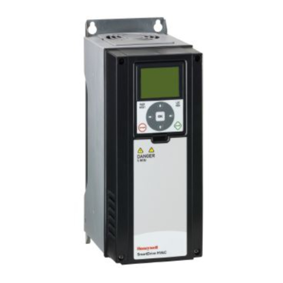
VSD2H Variable Speed Drives
Description
Variable motor speed drives suitable for HVAC applications
where the speed control of motors can be applied. They
convert fixed frequency and voltage from the mains supply to
variable frequency and voltage enabling motors to be used with
maximum efficiency resulting in significant energy savings.
The control keypad can be mounted on the front of the unit or
can be remotely connected by way of a 2 m cable and mounted
on a panel or used as a handheld unit.
The keypad accesses the startup wizard which facilitates the
the application configuration for the user (pump/fan, PID loops,
multi-pump, cascade control).
Physical
(dimensions in mm)
3 A to 105 A units (unit size MR4 to MR7) - wall mounting
A
ØF
D
ØG
D
ØF
For 140 to 310 A sizes see next page
VSD2H Variable Speed Drives Data Sheet TA201104 Issue 3, 08-Oct-2013
Variable Speed Drives
Features
▪ 380 to 480 Vac 3 phase
▪ current rating range from 3 A to 310 A
▪ IP21 and IP54 models available
▪ optional Trend system network interfaces (NXNI or NXIP)
▪ application configurable using wizard for a number pump or
fan scenarios
▪ real time clock fitted with battery
▪ integrated RFI filter for typical building installation
▪ versatile PC tools available
▪ slim, space-saving, "bookshelf" design
▪ varnished printed circuit boards to maximise reliability
IP21
C
S= supply cable
M= motor cable
C= control cable
Current (A)
3 to 12
128 328
16 to 31
144
38 to 61
195 557
72 to 105
237 660
140 to 205 290 966
261 to 310
480 1150 365 400 1122 9
* For MR8, MR9 detail see next page
VSD2H
IP54
S (ØH)
B (ØI)
M (ØH)
A
B
C
D
E
ØF ØG ØH ØI
190 100 313
7
419
214
115 406
7
229 148 541
9 15.5 40
259 190 645
9
343 217 947
9
Data Sheet
C (Ø25)
Frame
13
25
25
MR4
14
33
25
MR5
33
MR6
16
50
50
MR7
16
60
60
MR8*
16
59
59
MR9*
1
Advertisement
Table of Contents

Summary of Contents for TREND VSD2H
- Page 1 343 217 947 MR8* 261 to 310 480 1150 365 400 1122 9 MR9* ØF For 140 to 310 A sizes see next page * For MR8, MR9 detail see next page VSD2H Variable Speed Drives Data Sheet TA201104 Issue 3, 08-Oct-2013...
- Page 2 FunctionAlity The VSD2H range of variable speed drives provides 20 models (3 A to 310 A) for voltages from 380 to 480 Vac 3 phase with either IP21 or IP54 rating. Designed for use in the HVAC environment, they enable fans and motors to regulate delivery of air and water in variable flow applications.
- Page 3 (identified by letters A, B, D, E) of the control board. AO1+ (current) AO1- +24 Vin digital input RS485 A (-) ground isolation RS485 B (+) link VSD2H Variable Speed Drives Data Sheet TA201104 Issue 3, 08-Oct-2013...
- Page 4 Min. switching load Motor temperature TI1+ trip thermistor (PTC). = 4k7 ohms, Thermistor input If thermsisor circuit TRIP Measuring voltage = 3.5 V is not used it must TI1- be short-circuited VSD2H Variable Speed Drives Data Sheet TA201104 Issue 3, 08-Oct-2013...
- Page 5 Ethernet interface, NXIP. See NXNI data sheet TA200544 or NXIP data sheet TA200826 for details. Note that the NXNI allows the unit to be monitored by all Trend IQ controllers, but it can only be written to by IQ3, IQ4. or IQeco controllers.
- Page 6 Digital input isolation: The digital inputs (DI1 to DI6) can be real time clock: The VSD2H has a real time clock with timer isolated from ground by removing a link on the control board functions. The unit comes complete with a Real Time Clock as shown.
-
Page 7: Quick Setup
FirMwAre High Switching Frequency: The VSD2H is capable of providing the maximum power with high switching frequency. Full details of the firmware are diven in the VSD2H Application Benefit: Low audible noise from the motor. Manual TE201103. Prohibit frequency: Overriding the critical frequencies to Quick Setup avoid resonance. -
Page 8: Installation Procedure
The Trend VSD2H drive must be installed in a vertical position. It can be mounted on a wall or in an enclosure using four screws or bolts. The cooling airflow to the drive must not be blocked in any way, recirculation of air inside the enclosure should be avoided. -
Page 9: Control Connections
IQs (IC comms) and Supervisors (Text comms) - see order codes for details. Note that the NXNI allows the unit to be monitored by all Trend IQ controllers, but it can only be written to by IQ3, IQ4, or IQeco controllers. -
Page 10: Order Codes
:NX variable speed drive IQ system Lan on Ethernet interface 45 A (see NXIP data sheet) 61 A Acc/VSD2H/Door MountinG Kit :Kit to mount keypad unit on door; includes 2 m cable 72 A Acc/VSD2H/HAnD HelD Kit :Kit to produce hand held keypad unit; includes 2 m cable... -
Page 11: Specifications
13.2 VSD2H/3P-480/016.. 17.6 VSD2H/3P-480/023.. 25.3 VSD2H/3P-480/031.. 34.1 VSD2H/3P-480/038.. 41.8 18.5 VSD2H/3P-480/046.. 50.6 VSD2H/3P-480/061.. 67.1 VSD2H/3P-480/072.. 79.2 37.5 VSD2H/3P-480/087.. 95.7 37.5 VSD2H/3P-480/105.. 115.5 37.5 VSD2H/3P-480/140.. VSD2H/3P-480/170.. VSD2H/3P-480/205.. 225.5 VSD2H/3P-480/261.. 287.1 VSD2H/3P-480/310.. VSD2H Variable Speed Drives Data Sheet TA201104 Issue 3, 08-Oct-2013... - Page 12 Division of Honeywell Technologies Sàrl, Z.A. La Pièce, 16, 1180 Rolle, Switzerland by its Authorized Representative, Trend Control Systems Limited. Trend Control Systems Limited reserves the right to revise this publication from time to time and make changes to the content hereof without obligation to notify any person of such revisions or changes.
Need help?
Do you have a question about the VSD2H and is the answer not in the manual?
Questions and answers