
Related Manuals for Global Traffic Technologies Opticom 2100 Series

Summary of Contents for Global Traffic Technologies Opticom 2100 Series
- Page 1 Installation Manual May 2013 Opticom GPS System Vehicle Equipment Model 2100 Series...
-
Page 2: Table Of Contents
Vehicle Equipment Installation Instructions Table of Contents About This Manual ............................3 Intended Use ............................. 3 Technical Support ............................ 3 Safety Information ............................3 Label Locations ............................4 Safety Considerations ..........................5 FCC and IC Statement ..........................6 Description ................................ 6 Opticom™... -
Page 3: About This Manual
Vehicle Equipment Installation Instructions 1 About This Manual This manual provides step-by-step instructions for installing the Global Traffic Technologies Opticom™ GPS System* vehicle equipment. It is intended for use by installers, maintenance personnel, and others who are responsible for the installation and maintenance of the system. -
Page 4: Label Locations
Vehicle Equipment Installation Instructions 2.1 Label Locations There are fuse size safety labels, FCC/IC labels on the Opticom™ GPS System vehicle equipment. If a label is missing or cannot be read, please contact your dealer or the GTT Repair department for a replacement. Labels listing the fuse size are included with the installation kit and should be placed by the installer next to the fuse holders. -
Page 5: Safety Considerations
Vehicle Equipment Installation Instructions 2.2 Safety Considerations Please consider the following safety issues before beginning the installation of the Opticom™ GPS System vehicle equipment. Although we have compiled this list of common safety considerations, it should not be considered as complete. It is not intended to take the place of your good judgment, training, and experience. -
Page 6: Fcc And Ic Statement
Vehicle Equipment Installation Instructions 2.3 FCC and IC Statement FCC Statement: This device complies with part 15 of the FCC rules. Operation is subject to the following two conditions: (1) This device may not cause harmful interference, and (2) this device must accept any interference received, including interference that may cause undesired operation. -
Page 7: Vehicle Equipment
Vehicle Equipment Installation Instructions 3.2 Vehicle Equipment The Opticom™ GPS System vehicle equipment is intended for use on priority vehicles. The vehicle equipment consists of a Radio/GPS Control Unit (RGCU) containing a GPS receiver and a 2.4 GHz transceiver. The RGCU also provides an interface point to the vehicle wiring, and an external PC used for configuration and diagnostics. -
Page 8: Parts List
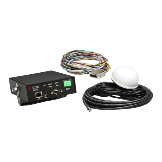
Vehicle Equipment Installation Instructions 3.3 Parts List The following is a list of components in the vehicle kit. See Figure 3-1 for more details. 1 Model 1050 Radio/GPS antenna • White 3” diameter dome with two 15’ cables. 5 *Model 2100 Series Radio/GPS Control Unit. •... -
Page 9: Features
Vehicle Equipment Installation Instructions 3.4 Features Opticom™ GPS system vehicle equipment has the following features: • Operates on 10-36 VDC • Sense line inputs 10-36 VDC • 25-foot interface cable for installation flexibility • Configurable Disable mode with multiple activation and operational behavior options. •... -
Page 10: Specifications
Vehicle Equipment Installation Instructions 3.5 Specifications • Opticom™ Model 2100 Series GPS vehicle control unit o Length: 7.25 in. (18.4 cm) o Width: 5.44 in. (13.8 cm) o Height: 1.63 in. (4.1 cm) o Weight: 1.2 lb. (0.54 kg) • Opticom™... -
Page 11: Installation
Vehicle Equipment Installation Instructions 4 Installation This section describes the installation of the Opticom™ GPS System vehicle equipment. Please read and fully understand the following paragraphs before starting the installation. • Before cutting or drilling any openings in the vehicle or light bar, draw a diagram showing placement, measurements, and dimensions. -
Page 12: Model 1050 Radio/Gps Antenna Installation
Vehicle Equipment Installation Instructions 4.1 Model 1050 Radio/GPS antenna installation The antenna cables are 15’ long. When choosing a location for the radio/GS antenna and the vehicle control unit, be sure that the cables are long enough to reach the location of the vehicle control unit. - Page 13 Vehicle Equipment Installation Instructions Figure 4-1. Mounting Radio/GPS Antenna on Priority Vehicle 1. Vehicle radio/GPS antenna 4. Radio and GPS antenna cables 2. Vehicle mounting surface 5. 5/8 to 3/4-inch mounting hole 3. Antenna nut 6. Antenna lock washer...
-
Page 14: Model 79Xhm, Model 79Xtm
Vehicle Equipment Installation Instructions 4.1.3 Model 79XHM, Model 79XTM WARNING The antenna has been approved for mobile applications where the antenna should be used at distances greater than 20 cm from the human body (with the exception of hands, wrists, feet and ankles). -
Page 15: Radio/Gps Control Unit (Rgcu) Installation
Vehicle Equipment Installation Instructions 4.2 Radio/GPS Control Unit (RGCU) Installation This section describes the installation of the Model 2100 Series Radio/GPS Control Unit. Notes: • The radio/GPS control unit must not be in the path of airbag deployment. • Use care when drilling holes to avoid drilling into undesirable locations. •... -
Page 16: Cable Connections
Vehicle Equipment Installation Instructions 4.3 Cable connections 1. Remove interior panels and headliners, as necessary, to provide access for cable routing. 2. Route the cables from the radio/GPS antenna (or 79XXM) through the vehicle to the back of the radio/GPS control unit. See Figure 4-4. 3. -
Page 17: Wiring Connections
Vehicle Equipment Installation Instructions Figure 4-5. Radio/GPS Control Unit Installation 1. Mounting bracket 3. Acorn nut (2) 2. Lock washer (2) 4. Radio/GPS control unit 5 Wiring Connections This section wiring describes the wiring connections in the vehicle. The connections are made via the Model 2171 vehicle interface harness. - Page 18 Vehicle Equipment Installation Instructions Pin Wire Color Wire Function Wire Size (AWG) White/Yellow J1708+ Blue Light Bar Sense or Ignition Switch 20 Brown Low Priority Gray Probe Priority Yellow/Blue Not Used White Disable Sense Green Right Turn Signal Sense Yellow Left Turn Signal Sense Black Ground (DC-)
-
Page 19: Power And Ground Connections
Vehicle Equipment Installation Instructions 5.1 Power and Ground Connections Notes: • The system will operate from +10-36 VDC. • In order for the GPS receiver to maintain an accurate location and for the vehicle equipment to start up quickly, the receiver requires a constant DC power source. •... -
Page 20: Activation Methods And Switch Settings
Vehicle Equipment Installation Instructions 5.2.1 Activation Methods and Switch settings There are three recessed switches on the back of the radio/GPS control unit. These switches are for controlling the function and behavior of the light bar/ignition sense input (Blue wire). Switch Position Function/Behavior IGNIT... -
Page 21: Emergency Vehicle Activation Methods
Vehicle Equipment Installation Instructions • * If the IGNIT LVL switch is set to GND, the blue wire must normally have +10-36 VDC power applied to it. Also set the IGNIT switch to 12-36V. o If not the unit will not shut off. 5.2.1.1 Emergency Vehicle Activation methods: •... -
Page 22: Turn Signal Sensing Connections
Vehicle Equipment Installation Instructions 5.3 Turn Signal Sensing Connections The turn signal sensing inputs operate by detecting the vehicle’s turn signal circuits. The turn signal sense wires may be connected to a pulsing turn signal circuit or a steady turn signal circuit. By default the radio/GPS control unit is looking for a pulsing signal on the turn signal circuit. -
Page 23: Disable Sense Connection
Vehicle Equipment Installation Instructions 5.4 Disable Sense Connection It is recommended that the disable sense wire be connected. It is important to provide an automatic method of disabling the vehicle equipment so that emergency vehicle drivers do not need to remember to shut off the equipment when arriving at the scene. If the disable sense is not wired and the driver does not manually shut the Opticom™... -
Page 24: Low Priority (Optional)
Vehicle Equipment Installation Instructions 5.5 Low Priority (optional) When Opticom™ vehicle equipment ships from the factory, the priority level (High or Low) is factory programmed. The user cannot permanently change this priority level. However, a high priority vehicle may be set to temporarily be a low priority vehicle. This feature is useful for traffic department maintenance vehicles that maintain Opticom™... -
Page 25: J1708 Connections (Optional)
Vehicle Equipment Installation Instructions 5.7 J1708 Connections (optional) This section describes the necessary connections and configuration to communicate between the Opticom™ GPS system vehicle equipment and other onboard devices such as an Automatic Vehicle Location (AVL). Skip this section if these connections are not to be used. J1708/J1587 is a communication protocol which allows communications between the Opticom™... -
Page 26: Gps Output (Optional)
Vehicle Equipment Installation Instructions 5.8 GPS Output (optional) The Opticom™ GPS system utilizes information from the constellation of GPS satellites. This data may also be used by other devices that are installed in an Opticom™ GPS equipped vehicle. This section provides details on the format of the GPS data as well as details on how to connect to the Opticom™... -
Page 27: Other Connections (Optional)
Vehicle Equipment Installation Instructions 5.9 Other connections (optional) No other wiring connections are needed. Some of the wires described in Table 5-1 are for future applications. Do not connect any wires not described in sections 5-1 to 5-8. 5.10 Model 2173 Adapter for using previous generation harness The Model 2173 adapter is available if you are upgrading from a Model 1020 or 1021 Vehicle Control Unit using a Model 1071 vehicle interface harness to a Model 2100 series Radio/GPS Control Unit. -
Page 28: Infrared Emitter Connections (Optional)
Vehicle Equipment Installation Instructions 6 Infrared Emitter connections (optional) Skip this section if you are not connecting an infrared emitter. The radio/GPS control unit contains a 6-pin terminal strip for connecting an Infrared emitter. When connected, the emitter will be able to be switched on and off by the radio/GPS control unit. When the radio/GPS control unit is put into disable mode, any emitter that is connected to it will also be turned off (disabled). - Page 29 Vehicle Equipment Installation Instructions 6. Connect the red wire to the red terminal. 7. Connect the black wire to the black terminal 8. Cut off, tape off, or insulate and secure the gray and blue wires. a. See note above 9.
-
Page 30: Configuration And Checkout
Vehicle Equipment Installation Instructions 7 Configuration and Checkout This section describes how to configure check out and verify the installed Opticom™ GPS vehicle. These installation instructions are the result of tests performed in our laboratory and we believe these tests to be accurate and complete. However, each installation involves variables that cannot be controlled or predicted. -
Page 31: Configuration Setup
Vehicle Equipment Installation Instructions Indicator Color/State Meaning ON/OFF Unit is powered off Switch Steady Green Unit is powered on Flashing Green once every Unit is in Disable mode two seconds Flashing Green two times Unit is in Broken mode per second STATUS Unit powered off or offline Steady Green... -
Page 32: Input Verification
Vehicle Equipment Installation Instructions 7.2 Input Verification Click on Diagnostics Link in the On-site software to see the discreet inputs section. This screen will allow you to monitor the state of various discreet inputs. If the discreet inputs are not seen in this screen, it will be necessary to rewire the inputs so that they are detected. -
Page 33: Disable Input Verification
Vehicle Equipment Installation Instructions 7.2.2 Disable Input Verification 1. Set the appropriate Disable Operating Mode and Turn Signal Triggering Mode using the On- site software. 2. Activate the disable switch and verify that the disable input changes form Off to On or On to Off. -
Page 34: Verifying Using An Intersection
Vehicle Equipment Installation Instructions 5. Open the vehicle heard screen and verify that you can hear the vehicle being tested. 6. Place the test vehicle into transmit test mode per step 3. 7. Reconnect to the vehicle being tested and verify that you can hear the test vehicle. 8. -
Page 35: Communication Ports
Vehicle Equipment Installation Instructions 8 Communication Ports Radio/GPS control units have multiple communication ports: • One RS-232(DB-9) port • One USB port • One Ethernet port • One J1708 port • One GPS Data output port • One CAN port (future) 8.1 RS-232 Communication Port There is one RS-232 communication port. -
Page 36: Ethernet Port
Vehicle Equipment Installation Instructions 8.3 Ethernet Port The default address for the Ethernet port is: IP Address 192.168.0.1 TCP Port 5000 UDP Port 6000 Table 8-3 Ethernet Port Default settings • The address and port numbers in the Radio/GPS Control Unit may be changed using the On-site software. -
Page 37: Troubleshooting
Vehicle Equipment Installation Instructions 9 Troubleshooting Table 9-1 shows the symptoms of Vehicle Equipment installation problems. The table also shows the possible causes of those problems and suggests solutions to correct them. Symptom Possible Cause Solution Vehicle control unit LEDs will Wiring incorrect. -
Page 38: Maintenance
Vehicle Equipment Installation Instructions Symptom Possible Cause Solution Unable to communicate with Communication cable not Check cable connection at vehicle control unit. connected. vehicle control unit and at computer. Baud rate/serial port incorrect. Using On-site, change baud rate or port number. Intersection alternates Vehicle brake light bulb shared Reconnect vehicle turn signal... - Page 39 157 Adelaide Street West of Global Traffic Technologies, LLC St. Paul, Minnesota 55128-5441 Suite 448 Please recycle. Printed in the U.S.A. 1-800-258-4610 Toronto, ON M5H 4E7 © Global Traffic Technologies, LLC 2013 651-789-7333 Canada All rights reserved. www.gtt.com 1-800-258-4610 79-1000-0746-0 Rev. C...
Need help?
Do you have a question about the Opticom 2100 Series and is the answer not in the manual?
Questions and answers