Table of Contents
Advertisement
Quick Links
ELcon
Construction, operational and functional description
Consulting & Engineering
EL-31
Replacement display kit
for the
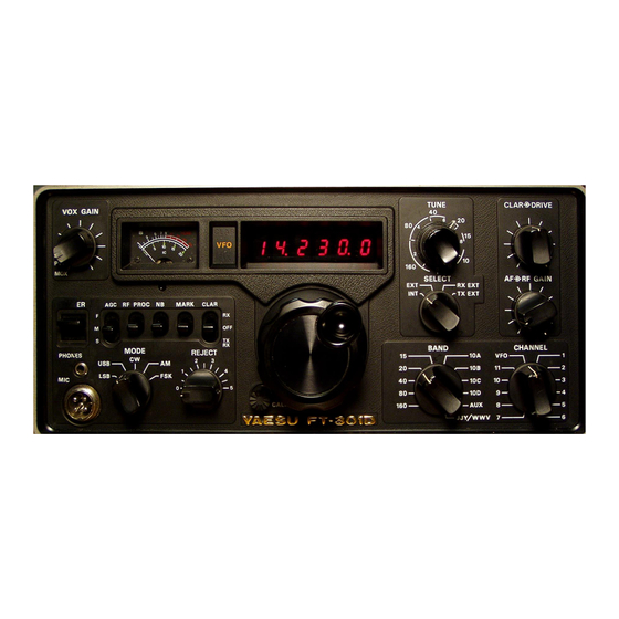
YAESU FT-301D
SW-Version 2.1b
April 7, 2019
Brunnhaldenstrasse 8
3510 Konolfingen
Switzerland
Telefon
+41 (0) 31 792 04 61
Fax
+41 (0) 31 792 04 62
E-Mail
info@elcon.ch
Shop
http://shop.elcon.ch
Advertisement
Table of Contents

Subscribe to Our Youtube Channel
Summary of Contents for Elcon EL-31
- Page 1 +41 (0) 31 792 04 61 Brunnhaldenstrasse 8 +41 (0) 31 792 04 62 Consulting & Engineering 3510 Konolfingen E-Mail info@elcon.ch Switzerland Shop http://shop.elcon.ch EL-31 Replacement display kit for the YAESU FT-301D Construction, operational and functional description SW-Version 2.1b April 7, 2019...
-
Page 2: Table Of Contents
Repair / Warranty ......................... 27 PCB assembly ........................28 Schematics ........................... 29 Important! Advices or tips for the correct function of the EL-31 Caution! The instructions must be observed carefully. April 7, 2019, © Elcon, Switzerland Page 2 / 29... -
Page 3: Introduction
Soldering is one of the most important aspects of setting up this device. A bad solder joint - even with a carefully assembled kit - can make it impossible to operate the unit and lead to frustration. April 7, 2019, © Elcon, Switzerland EL-31_V2.1b_en.docx Page 3 / 29... - Page 4 = 100 ±2% = 1’000 orange = 10’000 yellow = 100’000 green ±0.5% = 1’000’000 blue ±0.25% = 10'000’000 violet ±0.1% = 100'000’000 gray = 1'000'000’000 white Table 1 April 7, 2019, © Elcon, Switzerland Page 4 / 29 EL-31_V2.1b_en.docx...
-
Page 5: Parts Lists
PCB EL-31 PCB Version 1.0a [Component 15] Table 2 Component 1 Component 2 Component 3 Component 4 Component 5 Component 6 Component 7 Component 8 Component 9 Component 10 April 7, 2019, © Elcon, Switzerland EL-31_V2.1b_en.docx Page 5 / 29... -
Page 6: Step By Step Assembly And Testing Of Printed Circuit Boards
J2, Solder the 30 cm long white wire → This wire will be connected to the 13.8V supply voltage of the transceiver after installation of the display board into the FT-301D. April 7, 2019, © Elcon, Switzerland Page 6 / 29 EL-31_V2.1b_en.docx... -
Page 7: Initial Testing Of The Board
For example, if you set and save incorrect values in the voltage calibration procedure, the meter will indicate wrong values. But you can repeat the calibration procedures as many times as you want, until you get the correct result. April 7, 2019, © Elcon, Switzerland EL-31_V2.1b_en.docx Page 7 / 29... -
Page 8: Adjustment Of The Voltage Measurement Circuit
If your RF signal generator has a TTL-level output, the auxiliary interface circuit is not needed. You can connect the signal generator directly to the EL-31 P3 / Pin 3. For the injection of a sinusoidal test frequency an auxiliary circuit is required. This auxil- iary circuit is available in the transceiver FT-301D, but it is needed to carry out the fre- quency alignment on the not built-in display board. - Page 9 Press the numeric key no 3 on the remote control again. You see . Press the VOL+ or VOL- key until the display shows .. (last digit = 100Hz). April 7, 2019, © Elcon, Switzerland EL-31_V2.1b_en.docx Page 9 / 29...
-
Page 10: Conversion Of The Ft-301D
Remove the mounting screw behind the frequency setting knob (see Figure 3). Figure 3 Loosen the two screws securing the display device holder on top (do not remove entirely). Figure 4 April 7, 2019, © Elcon, Switzerland Page 10 / 29 EL-31_V2.1b_en.docx... -
Page 11: Installation Of The New Display Board In The Ft-301D
Route the white wire, which is soldered to the new display board, to the rear wall and sol- der it on the connection of the cable entry (see Figure 5). Figure 5 April 7, 2019, © Elcon, Switzerland EL-31_V2.1b_en.docx Page 11 / 29... - Page 12 1541D. This unit can be found on the bottom side behind the display unit. Using a small screwdriver, rotate the trim potentiometer until the display shows a stable frequency in the 20m band. Figure 7 April 7, 2019, © Elcon, Switzerland Page 12 / 29 EL-31_V2.1b_en.docx...
- Page 13 Turn the device over, so that the top is facing up. Take off the cover and insert the speaker wire again. Put the cover onto the device and secure it with the four plastic plugs. April 7, 2019, © Elcon, Switzerland EL-31_V2.1b_en.docx Page 13 / 29...
-
Page 14: Operation And Functions
3 Operation and functions The LED display EL-31 is primarily intended as a 1:1 replacement for the failure-prone origi- nal display module. With the modern microcontroller technology, it is relatively easy to imple- ment additional features and make the replacement even more worthwhile. -
Page 15: Menu Structure
All settings are stored in the microcontroller of the display. 3.3 Menu structure Operation is done via menus, which are shown in the figures below. Figure 9 Figure 10 April 7, 2019, © Elcon, Switzerland EL-31_V2.1b_en.docx Page 15 / 29... - Page 16 VOL+ / VOL- ff VOL+ / VOL- trff tr tr tr tr tr VOL+ / VOL- Figure 11 April 7, 2019, © Elcon, Switzerland Page 16 / 29 EL-31_V2.1b_en.docx...
-
Page 17: Modes
Since at frequencies of > 9.999.99 MHz the 6-digit display is no longer sufficient, the fre- quency is always displayed in the format ... The . in the one-MHz digit indicates that the display is permanently set at 10Hz format. April 7, 2019, © Elcon, Switzerland EL-31_V2.1b_en.docx Page 17 / 29... -
Page 18: Band Modifications (Band Switch Positions 160M, 15M Or Aux)
To ensure that the frequency display corresponds to the new frequency band again after a band modification, the diode matrix in the "Counter Mixer Unit PB-1541" could also be changed. However, this requires a lot of effort. The EL-31 display module allows various set- tings which correct the frequency display for the new band. - Page 19 d. (12m band) Press the Number key 8 or OK key again. is displayed again. Use the VOL+ or VOL- buttons to switch to mode. April 7, 2019, © Elcon, Switzerland EL-31_V2.1b_en.docx Page 19 / 29...
-
Page 20: Transverter Operation (Band Switch Positions 10A To 10D)
(50MHz to 432MHz) can be selected in the setup menu. The status (ON / OFF) of the transverter is signaled to the frequency display module and so the correct frequency is always displayed. April 7, 2019, © Elcon, Switzerland Page 20 / 29 EL-31_V2.1b_en.docx... -
Page 21: Voltage Display
Press the numeric key no 1 → this results in the “short“ output of the frequency; i.e. the frequency is emitted in kHz only (without the MHz-, 100Hz- und 10Hz- digits). April 7, 2019, © Elcon, Switzerland EL-31_V2.1b_en.docx Page 21 / 29... -
Page 22: Morse Readout Of Voltage
VOL+ or VOL- key. Change to the Press the numeric key no 0 (zero) → this results in the output of the voltage; i.e. the voltage is emitted in V.100mV. April 7, 2019, © Elcon, Switzerland Page 22 / 29 EL-31_V2.1b_en.docx... -
Page 23: Software Update
PC to EL 31 are needed. The required software and all necessary drivers can be downloaded from the web- site http://shop.elcon.ch Unzip the zip file into the directory "EL-31 USB-Loader Setup" and open the file "EL-31 USB-Loader Setup \ cd.htm with the Internet Explorer, Figure 13 4.1.1 Installing the USB-updater software on the PC... - Page 24 With the Device Manager, the result can be checked under "Custom USB Devices" (see ) → there is a new entry "Elcon USB Bootloader" as long as the connection with the EL-31 exists. The Device Manager can be started directly from the Web page (see Figure 13).
-
Page 25: Transferring The Software Updates In The El-31
Click to button to connect the USB-updater program automatically with the EL-31. The following "Auto Detect" window should show a successful detection of the EL-31 USB boot loader in order to perform the software update. Confirm with the key Figure 16 Load the update file EL 31xxx.ELC or EL 31xxx.HEX with <File / Open…>... -
Page 26: Appendix
Figure 19 If the data transmitting is not successful, check the correct USB connection to the EL 31 by using the Device Manager and verify if the “Elcon USB Bootloader” is listed in "Custom USB Devices" section. Then repeat the data update. -
Page 27: Repair / Warranty
In all cases the transport costs of the kit shall be borne by you. April 7, 2019, © Elcon, Switzerland EL-31_V2.1b_en.docx Page 27 / 29... -
Page 28: Pcb Assembly
5.4 PCB assembly Figure 20 Figure 21 April 7, 2019, © Elcon, Switzerland Page 28 / 29 EL-31_V2.1b_en.docx... -
Page 29: Schematics
5.5 Schematics April 7, 2019, © Elcon, Switzerland EL-31_V2.1b_en.docx Page 29 / 29...
Need help?
Do you have a question about the EL-31 and is the answer not in the manual?
Questions and answers