Advertisement
Quick Links
Advertisement

Summary of Contents for Nimco WK300 Series
- Page 3 Contents Page 4 General Information Page 5 Assembly Dimensions Page 6 Joystick Movements Page 7 Technical Data Page 8-9 Order Code Page 10 Handgrips Page 11-12 Configurations Page 13 Optional Handgrip Inserts Page 14 Assembly Instructions Directional Control Valve Series CV 652...
-
Page 4: General Information
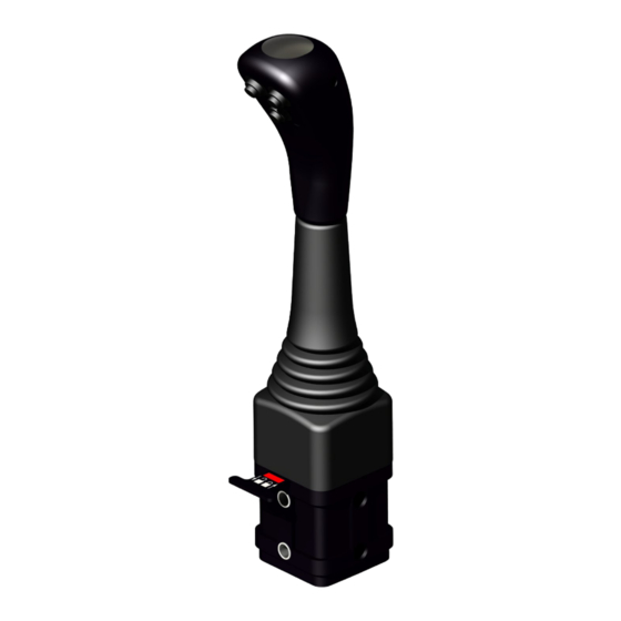
• A secure and easy to reach locking mechanism with clearly indicated warning signs • Electric push buttons rated at 3M cycles and 12V, 6A for direct connection to any of Nimco’s circuit selector valves. • The push buttons are at high quality and will withstand rough environment •... -
Page 5: Assembly Dimensions
Assembly Dimensions Directional Control Valve Series CV 652... - Page 6 Joystick Movement Cable 2 Cable 1 Spool 1 Spool 2 Cable 2 Cable 1 Spool 1 Spool 2 Directional Control Valve Series CV 652...
-
Page 7: Technical Data
Technical Data A-side B-side Code Type Type Code Spring centered. 3W can be used with A-side Detent in pos. controls 9, 10, 1, 2 and 3. 13 and 14. Spring centered. Detent in pos. 4 4W can be used Spring centered. with A-side Detent in pos. - Page 8 Order Code WK300 Article No. Product Hangrip type Description Complete joystick 11414-3S WK-300-1-0 Black grip JS without el. switch 11518-3S WK-300-1-1 Black grip JS with 1 el. switch 11519-3S WK-300-1-2 Black grip JS with 2 el. switches 11520-3S WK-300-1-3 Black grip JS with 3 el.
- Page 9 Order Code WK350 Article No. Product Hangrip type Description Complete joystick 11630-3S WK-350-1-0 Black grip JS without el. switch 11631-3S WK-350-1-1 Black grip JS with 1 el. switch 11632-3S WK-350-1-2 Black grip JS with 2 el. switches 11633-3S WK-350-1-3 Black grip JS with 3 el.
- Page 10 Handgrips Black grip only 11375-3S WKG-1-0 Handgrip without el. switch 11453-3S WKG-1-1 Handgrip with 1 el. switch 11454-3S WKG-1-2 Handgrip with 2 el. switches 11455-3S WKG-1-3 Handgrip with 3 el. switches Electric exchange plates for Black Grip 11374-4K WKEP-1-0 Plate without el. Switch 11515-4S WKEP-1-1 Plate with 1 el.
- Page 11 Configurations Exchangeable plate Changing the plate is eased by pre- mounted switches and electric cable. Inside thread M14 x 1.5 L=22 mm Wiring Diagram one button Directional Control Valve Series CV 652...
- Page 12 Configurations Wiring Diagram two switches Wiring Diagram three switches Directional Control Valve Series CV 652...
- Page 13 Optional Handgrip Inserts On the top part of the handgrip is a transparent cover. The handgrip comes with the Nimco logo or a movement diagram for front loader application as standard, but the customer can choose to integrate a specific print under the clear plastic cover.
- Page 14 Assembly Instructions Place the two spacers in the desired position. Pull out the security lock and draw the cables through the two holes in the housing. Insert the cable joints and the pivot post in the yoke. Push the cable joints and pivot post down into the housing. Fasten the pivot post by assembling the screw and tightening it to 6-7 Nm using a 5 mm Allen wrench.
-
Page 16: Hydraulic Systems
Hydraulic systems Nimco Controls Nimco Controls Europe North America & Asia 71-75 Shelton Street Corporate Headquarters Covent Garden, London 1500 S. Sylvania Avenue (USA) WC2H 9JQ United Kingdom Sturtevant, WI 53177 Phone: +44 20 3772 4540 Phone: 262-884-0950 salesusa@nimcous.com saleseurope@nimco.se •...
Need help?
Do you have a question about the WK300 Series and is the answer not in the manual?
Questions and answers