
Summary of Contents for VALMETAL H Series
- Page 1 INC. FARM EQUIPMENT MANUFACTURER ROUND BALE GRINDER MODEL H OPERATOR'S MANUAL AND PARTS BOOK...
- Page 2 Obligation under this warranty shall extend for a period of 1 year (12 months) follow- ing the date of delivery to the original purchaser and shall be limited to replacement or repair at Valmetal’s choice of any parts found to be defective upon inspection by Valmetal.
- Page 3 SERIAL NUMBER LOCATION Always state the serial number of your Valmetal Round Bale Grinder when ordering parts or requesting service or other information. The serial number plate is located where indicated. Please mark the number in the space provided for easy reference.
-
Page 4: Table Of Contents
Page Contents SECTION 1 INTRODUCTION..................SECTION 2 SAFETY..........................GENERAL SAFETY........................OPERATING SAFETY......................... MAINTENANCE SAFETY......................HYDRAULIC SAFETY........................TRANSPORT SAFETY........................ STORAGE SAFETY........................TIRE SAFETY..........................SAFETY DECALS........................SIGN-OFF FROM......................... SECTION 3 SAFETY DECAL LOCATIONS............... SECTION 4 OPERATION..................... TO THE NEW OPERATOR OR OWNER.................. -
Page 5: Section 1 Introduction
This equipment has been designed and manufactured to meet the needs of a discriminating buyer for the effi- cient grinding of large round bales. Safe, efficient and trouble free operation of your ValMetal Round Bale Grinder requires that you and anyone else who will be operating or maintaining the Grinder, read and understand the Safety, Operation, Maintenance and Trouble Shooting information contained in the Operator's Manual. - Page 7 ATTENTION! BECOME ALERT! The Safety Alert symbol identifies important YOUR SAFETY IS INVOLVED! safety messages on the ValMetal Round Bale Grinder and in the manual. When you see this symbol, be alert to the possibility of personal injury or death. Follow the instructions in the safety message.
-
Page 8: Safety
1 . Read and understand the Operator's Manual and YOU are responsible for the SAFE operation and all safety signs before operating, maintaining or maintenance of your ValMetal Round Bale Grinder. adjusting the Grinder. YOU must ensure that you and anyone else who is going to operate, maintain or work around the 2. -
Page 9: Operating Safety
SAFETY OPERATING SAFETY MAINTENANCE SAFETY 1. Follow ALL the operating, maintenance and 1. Read and understand the Operator's Manual and safety information in the manual. all safety signs before operating, servicing, adjusting, repairing, unplugging or filling. 2. Support the machine with blocks or safety stands when changing tires or working beneath it. -
Page 10: Hydraulic Safety
SAFETY HYDRAULIC SAFETY TRANSPORT SAFETY 1. Always place all tractor hydraulic controls in 1. Make sure you are in compliance with all local neutral before dismounting. regulations regarding transporting equipment on public roads and highways. 2. Make sure that all components in the hydraulic system are kept in good condition and are clean. -
Page 11: Storage Safety
SAFETY STORAGE SAFETY SAFETY DECALS 1. Keep safety decals and signs clean and legible 1. Store the Grinder in an area away from human at all times. activity. 2. Replace safety decals and signs that are missing 2. Do not permit children to play on or around the or have become illegible. -
Page 12: Sign-Off From
SAFETY 2.9 SIGN-OFF FORM ValMetal follows the general Safety Standards specified by the Society of Automotive Engineers (SAE) and the Occupational Safety and Health Administration (OSHA). Anyone who will be operating and/or maintain- ing the Round Bale Grinder must read and clearly understand ALL Safety, Operating and Maintenance infor- mation presented in this manual. -
Page 13: Safety Decal Locations
SAFETY DECALS SECTION 3 SAFETY DECAL LOCATIONS The types of decals and locations on the equipment are shown in the illustration below. Good safety requires that you familiarize yourself with the various Safety Decals, the type of warning and the area, particular func- tion related to that area, that requires your SAFETY AWARENESS. - Page 14 SAFETY DECALS The types of decals and locations on the equipment are shown in the illustration below. Good safety requires that you familiarize yourself with the various Safety Decals, the type of warning and the area, or particular function related to that area, that requires your SAFETY AWARENESS. Think SAFETY! Work SAFELY! WARNING HIGH-PRESSURE FLUIDE HAZARD...
- Page 15 SAFETY DECALS The types of decals and locations on the equipment are shown in the illustration below. Good safety requires that you familiarize yourself with the various Safety Decals, the type of warning and the area, or particular function related to that area, that requires your SAFETY AWARENESS. Think SAFETY! Work SAFELY! WARNING WARNING...
- Page 16 SAFETY DECALS The types of decals and locations on the equipment are shown in the illustration below. Good safety requires that you familiarize yourself with the various Safety Decals, the type of warning and the area, or particular function related to that area, that requires your SAFETY AWARENESS. Think SAFETY! Work SAFELY! DANGER ROTATING PART HAZARD...
-
Page 17: Operation
TO THE NEW OPERATOR OPERATING SAFETY OR OWNER Read and understand the Operator's Manual ValMetal Round Bale Grinder are designed to effi- and all safety signs before operating, servicing, adjusting, repairing, unplugging or filling. ciently grind large bales. Hay, straw, green feed and paper can be used in this Grinder. -
Page 18: Machine Components
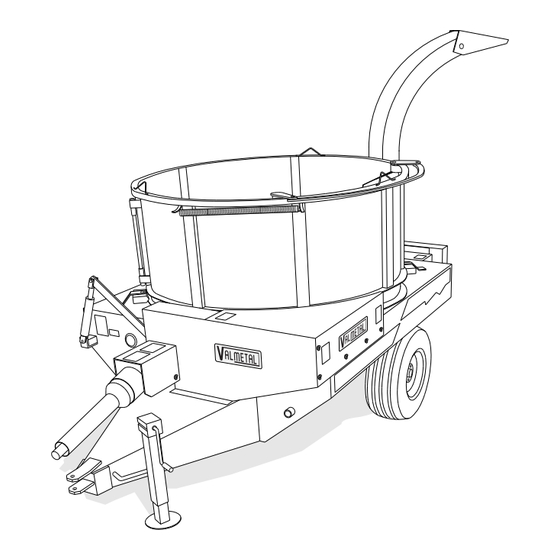
MACHINE COMPONENTS A chute or spout is attached to the opening to direct The ValMetal Round Bale Grinder is a large rotating the flow of material. A moveable deflector on the top tub over a spinning rotor that is equipped with sickle of the spout is used to direct the flow. -
Page 19: Break-In
OPERATION BREAK-IN Although there are no operational restrictions on the C. After grinding 10 and 50 bales: machine when used for the first time, it is recom- 1. Tighten all wheel bolts, fastener and other mended that the following mechanical items be hardware to their specified torque. -
Page 20: Pre-Operation Checklist
OPERATION PRE-OPERATION CHECKLIST Efficient and safe operation of the ValMetal Round Bale Grinder requires that each operator reads and under- stands the operating procedures and all related safety precautions outlined in this section. A pre-operation checklist is provided for the operator. It is important to follow this checklist in order to ensure personal safety and the good mechanical condition of the machine. -
Page 21: Equipment Matching
OPERATION 3. PTO Shaft: The tractor must be equipped with EQUIPMENT MATCHING a 1 3/8 inch, 6 spline 540 RPM PTO. To insure the safe and reliable operation of the Grinder, it is necessary to use it with a tractor of IMPORTANT appropriate size and power. -
Page 22: Controls
OPERATION CONTROLS Before starting to work, all operators should familiar- ize themselves with the location and function of the controls on the tractor and machine as appropriate. 1. PTO Control Lever: On tractor. 2. Throttle: On tractor. 3. Hydraulic Controls: On tractor. 4. -
Page 23: Attaching / Unhooking Machine
OPERATION ATTACHING / UNHOOKING MACHINE When attaching the machine, follow this procedure: 3. Use the jack to raise the hitch to align the clevis with the tractor drawbar. See figure 7. 1. Clear the area of bystanders, especially small children. 4. - Page 24 OPERATION 6. Install only a drawbar pin (Fig 8 "B") that has 9. Be sure the tractor is equipped with 1 3/8 inch 6 provisions for a mechanical retainer such as a spline shaft. Klik pin. 10. Check that the driveline telescopes easily and 7.
-
Page 25: Operating
OPERATION 3. Review and follow the pre-operation checklist OPERATING (See Section 4.4). Although the Grinder is simple and easy to use it is 4. Position the machine at the work site such that: recommended that the operator reviews this section frequently to stay familiar with the recommended safe a. - Page 26 OPERATION 5. Material: The Grinder is designed to shred hay, g. Place bale towards the back side of the tub. straw, haylage, hay silage and paper during operation. Bales containing rocks, stones, h. Close and latch tub doors. pieces of metal, roots, wire, twine, plastic wrapping or mesh must not be used.
- Page 27 OPERATION C. Important loading instructions. IMPORTANT! Never load the tub while the machine is running! Always stop the PTO before loading the machine. Always retract baffles before loading bale (figure. 13). Then release the winch. Fig. 15 RIGHT WAY TO LOAD BALE Fig.
- Page 28 OPERATION 7. Starting machine: a. Clear the area of bystanders. IMPORTANT Be sure the winch has been released so the baffles are free to extend and move the bale during operation. b. Place all controls in neutral and set park brake before starting tractor.
- Page 29 OPERATION 9. Over Running Clutch An over running clutch is located on the PTO shaft on the machine. It protects the braking system on the output shaft of tractor when stopping the PTO shaft of tractor. When the PTO shaft of tractor is stopped, the momentum of the heavy rotor could actually damage the brake system.
- Page 30 OPERATION 14. Hearing protection: All operators should wear appropriate hearing protection to prevent long term hearing loss. The noise level can be quite high with the engine running and the action of the blower. Be prepared. Wear hearing protection at all times.
- Page 31 OPERATION Fig. 23 MANGER FEEDING...
-
Page 32: Transporting
Electrocution can occur without machine before transporting. direct contact. ValMetal Round Bale Grinders are designed to be easily and conveniently moved from place to place. When transporting, follow this procedure: 1. Be sure all bystanders are clear of the machine. -
Page 33: 4.10 Storage
OPERATION 4.10 STORAGE STORAGE SAFETY 1. Store the Grinder in an area away from human activity. 2. Do not permit children to play on or around the stored machine. 3. Make sure the unit is sitting, or blocked up firm and solid and will not tip or sink into a soft area. - Page 34 OPERATION...
-
Page 35: Service And Maintenance
SERVICE & MAINTENANCE SECTION 5 SERVICE AND MAINTENANCE MAINTENANCE SAFETY 5.1 SERVICE 1. Follow ALL the operating, maintenance and 5.1.1 FLUIDS AND LUBRICANTS safety information in the manual. 1. Grease Use an SAE multi purpose high temperature 2. Support the machine with blocks or safety grease with extreme pressure (EP) perfor- stands when changing tires or working mance. -
Page 36: Servicing Intervals
SERVICE & MAINTENANCE 5.1.3 SERVICING INTERVALS 1 MONTH OR 75 BALES Lubricate PTO driveline shaft (2 locations). Fig. 24 PTO DRIVELINE SHAFT 3 MONTHS OR 200 BALES 1. Check gearbox oil level. Add gearbox oil (SAE90) if necessary. Check oil level through cap “B”. - Page 37 SERVICE & MAINTENANCE 3 MONTHS OR 200 BALES 1. Lubricate PTO driveline (2 locations). See Fig. 24. 2. Lubricate sealed bearings with 1 shot of grease: A. Front rotor bearing. B. Auger bearing. WARNING Machine is shown with guard removed for illustrative purposes only.
- Page 38 SERVICE & MAINTENANCE E. Two (2) jack shaft bearings. F. Front blower bearing. G. Tub drive chain lubrication (use spray chain grease) (figure 29). H. Auger drive chain lubrication (figure 28). Fig. 27 JACK SHAFT BEARING 3. Check belt and roller chain tension. Replace springs or adjust anchor nut as required.
- Page 39 SERVICE & MAINTENANCE 2 Years or 2000 Bales 1. Replace gearbox oil. Use SAE90 gearbox oil or the equivalent. You must remove the gearbox in order to change the oil (refer to section 5.2.3) Fig. 31 GEARBOX...
-
Page 40: Service Record
SERVICE & MAINTENANCE 5.1.4 SERVICE RECORD See Lubrication and Maintenance sections for details of service. Copy this page to continue record. ACTION CODE: CHECK REPLACE LUBRICATE HOURS SERVICED BY MAINTENANCE 1 MONTH OR 75 BALES L PTO Driveline Shaft (2) Gearbox Oil Level 3 MONTHS OR 200 BALES L PTO Driveline (2) -
Page 41: Maintenance
SERVICE & MAINTENANCE MAINTENANCE 5.2.1 KNIVES REPLACEMENT The knives are located on the rotor in the bottom of the tub. After long periods of use, they can wear. They can also be damaged when a hard object goes through the machine. If worn or damaged, they will have to be replaced. -
Page 42: Belt And Roller Chains
5. If this does not work, the roller chain or belt must be replaced. 6. To replace, remove spring and remove the belt or chain. 7. Replace with genuine ValMetal replacement parts. NOTE Use only matched belts for each multiple belt. -
Page 43: Gearbox Oil
SERVICE & MAINTENANCE 9. Add oil through the fill plug until oil starts to come 5.2.3 GEARBOX OIL out of the level plug hole. The oil level in the gearbox must be checked every 3 10. Tighten all plugs. months or after 200 bales to insure that the gears have proper lubrication. -
Page 44: Breather Cleaning
SERVICE & MAINTENANCE 5.2.4 BREATHER CLEANING The breather must be able to vent to atmospheric conditions during the heating and cooling cycles while operating. If it cannot, oil will seep out the seals and the machine will run low on oil. Prolonged operation with low oil levels will damage the internal working components. - Page 45 SERVICE & MAINTENANCE 5.2.5. OVER RUNNING CLUTCH & SHEAR PINS The Over Running Clutch is pre-set from the factory and does not require adjustment. The machine is also equipped with 2 shear pins. The PTO shear pin is located on the PTO drive (figure 38) and the auger shear pin is located at the end of the auger shaft (figure 39).
- Page 46 SERVICE & MAINTENANCE...
-
Page 47: Section 6 Trouble Shooting
TROUBLE SHOOTING SECTION 6 TROUBLE SHOOTING The ValMetal Round Bale Grinder uses a rotor with sickle sections to grind round bales into small pieces. It is a reliable system that requires minimal maintenance. In the following section, we have listed many of the problems, causes and solutions to the problems that you may encounter. - Page 48 TROUBLE SHOOTING PROBLEM CAUSE SOLUTION Poor grinding production rate. Broken knives. Replace knives. Knives covered. Remove entangled material. Grate too high. Lower grate. Baffles closed. Release baffles to turn bale. Tub won't turn. Drive problem. Replace belt. Repalce spring tensioner. Replace gearbox.
-
Page 49: Specifications
SPECIFICATIONS SECTION 7 SPECIFICATION MECHANICAL MODEL H-5500 H-5600 Overall Length: 163" 175" (414 cm) (444 cm) Overall Width: 90" 102" (229 cm) (259 cm) Height 74" 80" (without Chute): (188 cm) (203 cm) Height 106" 106" (with Chute): (269 cm) (269 cm) Tub Dimentions: 36"... -
Page 50: Bolt Torque
SPECIFICATIONS BOLT TORQUE CHECKING BOLT TORQUE The tables shown below give correct torque values for various bolts and capscrews. Tighten all bolts to the torques specified in chart unless otherwise noted. Check tightness of bolts periodically, using bolt torque chart as a guide. Replace hardware with the same strength bolt. ENGLISH TORQUE SPECIFICATIONS Bolt Bolt Torque*... -
Page 51: Hydraulic Fitting Torque
SPECIFICATIONS HYDRAULIC FITTING TORQUE TIGHTENING FLARE TYPE TUBE FITTING* 1. Check flare and flare seat for defects that might cause leakage. 2. Align tube with fitting before tightening. 3. Lubricate connection and hand tighten swivel nut until snug. 4. To prevent twisting the tube(s), use two wrenches. -
Page 52: Hydraulic Circuit
SPECIFICATIONS HYDRAULIC CIRCUIT GRATE CYLINDERS TO TRACTOR... - Page 54 CHASSIS FRAME...
- Page 55 AGRI-CHOPPER (MOD:5500-H & 5600-H) REF. PART NO DESCRIPTION 17A50-0000 BODY (MOD.5500) 17A50-0002 BODY (MOD:5600) 17A01-1550 TUB BEARING GUARD 17A05-2020 BEARING HOLDER'S BRACKET 17A55-0005 TUB BEARING COMPL."BEARING INCLUDED" 17A21-0000 TUB BEARING 14C75-0070 BALL BEARING 6205-2RS X Ø 1" 17A09-1220 BUSHING 1" Dia. X Ø 3/4" X 2.3/8" LG 17A09-0500 FLAT WASHER 1 3/4"...
- Page 56 AGRI-CHOPPER (MOD:5500-H & 5600-H) REF. PART NO DESCRIPTION 09A41-0900 SQUARE KEY 3/8" X 3/8" X 1 1/2" LG 17A55-0235 SHEAR PIN HOLDER COMPL."BOLT AND NUT INCLUDED" 17A55-0380 SHEAR BOLT COMPL.1/4"-20 X 1 1/2" LG "NUT AND FLAT WASHER INCLUDED" 17A37-1374 BEFORE -06/94 #13625- CHAIN #60 X 66"+ 1/2 MAILLE LG (VIS 12"Dia.)
- Page 57 AGRI-CHOPPER (MOD:5500-H & 5600-H) REF. PART NO DESCRIPTION 17A36-0600 SPROCKET 80B18 14C62-0006 TAPERED QD BUSHING SD 1 3/8" KW 5/16" 13C85-0003 EXTENSION SPRING 1 1/2" Dia. X 6 1/2" LONG 17A50-0055 BOLT 7/16"-14 X 5 1/2" LG (SPECIAL) 17A55-0040 SPROCKET 80B17 X Ø 1" COMPL."BEARING INCLUDED" 17A36-0605 SPROCKET 80B17 14C75-0070...
- Page 58 CHASSIS (SUITE) FRAME (CONT'D)
- Page 59 AGRI-CHOPPER (MOD:5500-H & 5600-H) REF. PART NO DESCRIPTION 17A50-0005 FINE CUT GRATE (MOD. 5500) 17A50-0010 FINE CUT GRATE (MOD. 5600) 17A50-0240 GRATE (PAPER OPTION) MOD.5500 17A50-0245 GRATE (PAPER OPTION) MOD.5600 09A41-0900 SQUARE KEY 3/8" X 3/8" X 1 1/2" LG 17A55-0165 ROTOR COMPL."STANDARD"...
- Page 60 AGRI-CHOPPER (MOD:5500-H & 5600-H) REF. PART NO DESCRIPTION 17A50-0300 ROTOR SHAFT (PAPER OPTION) MOD. 5500 17A50-0345 HEAVY DUTY KNIVES 01C37-0059 BOLT HEX.5/16"-24 X 7/8" LG (GRADE 8) 01C94-0002 STOVER LOCKNUT 5/16"-24 17A55-0190 ROTOR COMPL."STANDARD" (PAPER OPTION) 180 KNIVES (MOD.5600) 17A50-0305 ROTOR SHAFT (PAPER OPTION) MOD.5600 17A50-0345 HEAVY DUTY KNIVES...
- Page 61 AGRI-CHOPPER (MOD:5500-H & 5600-H) REF. PART NO DESCRIPTION 17A50-0085 AFTER -06/94 #13625- AUGER 16" Dia. (MOD.5600) 17A11-3515 AUGER'S SPACER BUSHING 17A55-0295 FRONT GUARD COMPL."STICKER INCLUDED" (MOD.5500) 17A55-0296 FRONT GUARD COMPL."STICKER INCLUDED" (MOD.5600) 17A55-0291 GEAR BOX GUARD "STICKER INCLUDED" (MOD.5500) 17A55-0292 GEAR BOX GUARD "STICKER INCLUDED"...
- Page 62 SOUFFLEUR (MODÈLE H) BLOWER (MODEL H)
- Page 63 AGRI-CHOPPER (MOD:5500-H & 5600-H) REF. PART NO DESCRIPTION 14C70-0012 WHEEL 15" COMPL. 14C70-0052 TIRE 14C70-0009 14C70-0016 TUBE 17A55-0100 WHEEL'S HUB COMPL. 17A46-0615 14C70-0014 TAPERED BEARING 14C70-0017 SEAT FOR TAPERED BEARING 14C70-0015 TRUST BEARING 14C70-0018 SEAT TRUST BEARING 14C70-0010 SEAL 14C70-0060 FLAT WASHER 1 3/4"...
- Page 64 AGRI-CHOPPER (MOD:5500-H & 5600-H) REF. PART NO DESCRIPTION 17A42-0010 BEFORE -02/97 #16436 JACK SHAFT PROTECTOR 1 1/4" Dia. X 10 3/8" LG 17A42-0025 AFTER -02/97 #16436 JACK SHAFT PROTECTOR 2 3/8" Dia. X 10 1/8" LG 14C75-0034 BEFORE -02/97 #16436 PILLOW BEARING UCP 207-20 X Ø...
- Page 65 AGRI-CHOPPER (MOD:5500-H & 5600-H) REF. PART NO DESCRIPTION 13C85-0022 GALV. RESSORT 1 3/8" Dia. X 9 1/2" LG 17A55-0321 TOP BELT'S GUARD "STICKER INCLUDED" 17A42-0105 NYLON RING 17A05-1100 ROTOR COVER BRACKET 17A50-0110 BACK COVER (ROTOR) 17A50-0330 BACK HYDRAULIC CYLINDRE ARM 14C75-0028 BEFORE -03/99 #19306-...
- Page 66 CUVE...
- Page 67 AGRI-CHOPPER (MOD:5500-H & 5600-H) REF. PART NO DESCRIPTION 17A55-0299 ROUND TUB COMPL."STICKER INCLUDED" (MOD:5500) 17A55-0300 ROUND TUB COMPL."STICKER INCLUDED" (MOD:5600) 17A55-0278 RIGHT DOOR COMPL."STICKER INCLUDED" (MOD:5500) 17A55-0279 RIGHT DOOR COMPL."STICKER INCLUDED" (MOD:5600) 17A55-0276 LEFT DOOR COMPL."STICKER INCLUDED" (MOD:5500) 17A55-0277 LEFT DOOR COMPL."STICKER INCLUDED" (MOD:5600) 17A50-0185 HINGE'S (MOD.5500) 17A50-0190...
- Page 68 AGRI-CHOPPER (MOD:5500-H & 5600-H) REF. PART NO DESCRIPTION 17A05-0000 RUBBER BRACKET (MOD:5500) 17A05-0005 RUBBER BRACKET (MOD:5600) 17A42-0035 RUBBER SEAL (MOD:5500) 17A42-0040 RUBBER SEAL (MOD:5600) 01C17-0006 HEX.BOLT 1/4"-20 X 1" LG (GRADE 2) (MOD:5500) 01C17-0006 HEX.BOLT 1/4"-20 X 1" LG (GRADE 2) (MOD:5600) 01C96-0009 HEX.NUT BLOC.NYLO.NC Z 1/4"-20 (MOD:5500) 01C96-0009...
- Page 69 CHUTE MANUELLE MANUAL CHUTE...
- Page 70 AGRI-CHOPPER (MOD:5500-H & 5600-H) REF. PART NO DESCRIPTION 17A55-0342 UNLAODING CHUTE'S BASE COMPL.(MANUAL) "STICKER AND RUBBER HANDLE INCLUDED" 13C15-0009 RUBBER HANDLE 17A55-0340 MANUAL DEFLECTOR CONTROL HANDLE W/RUBBER 17A50-0225 MANUAL DEFLECTOR CONTROL HANDLE WO/RUBBER 13C15-0009 RUBBER HANDLE ONLY 17A50-0215 SQUARE STEEL ELBOW 90 13C85-0008 SPRING 7/8"...
- Page 71 CHUTE HYDRAULIQUE (ROTATION ET DÉFLECTEUR) HYDRAULIC CHUTE (ROTATION AND DEFLECTOR)
- Page 72 AGRI-CHOPPER (MOD:5500-H & 5600-H) REF. PART NO DESCRIPTION 17A50-0215 SQUARE STEEL ELBOW 90 17A55-0362 SAFETY GARDE "STICKER INCLUDED" 17A55-0361 HYDRAULIC CHUTE BASE COMPL.(DEFLECTOR AND ROTATION) "STICKER INCLUDED" 17A50-0220 DÉFLECTOR 17A42-0145 NYLON SPACER 17A50-0275 HYDRAULIC MOTOR BRACKET 14C45-0005 HYDRAULIC MOTOR 17A50-0280 DRIVE GEAR 17A01-1580 TAPER WASHER...
- Page 73 CHUTE SEMI-HYDRAULIQUE (ROTATION) SEMI-HYDRAULIC CHUTE (ROTATION)
- Page 74 AGRI-CHOPPER (MOD:5500-H & 5600-H) REF. PART NO DESCRIPTION 17A50-0215 SQUARE STEEL ELBOW 90 17A55-0362 SAFETY GARDE "STICKER INCLUDED" 17A55-0372 CHUTE BASE COMPL.(HYDRAULIQUE ROTATION) "STICKER INCLUDED" 17A50-0220 DÉFLECTOR 17A42-0145 NYLON SPACER 17A50-0275 HYDRAULIC MOTOR BRACKET 14C45-0005 HYDRAULIC MOTOR 17A50-0280 DRIVE GEAR 17A01-1580 TAPER WASHER 17A45-6000...
- Page 75 CHUTE MANUELLE (DÉFLECTEUR) MANUAL CHUTE (DEFLECTOR)
- Page 76 AGRI-CHOPPER (MOD:5500-H & 5600-H) REF. PART NO DESCRIPTION 17A55-0373 MANUAL UNLAODING CHUTE'S BASE COMPL."STICKER AND HANDLE RUBBER INCLUDED" 13C15-0009 RUBBER HANDLE 17A50-0215 SQUARE STEEL ELBOW 90 13C85-0008 SPRING 7/8" Dia. X 5" LG 17A50-0220 DÉFLECTOR 17A42-0140 CABLE GUIDE 17A55-0131 DEFLECTOR CABLE 65" LG COMPL."MALLEABLE WIRE ROPE INCLUDED" 17A50-0260 HYDRAULIC CYLINDER "SPECIAL"...
- Page 77 DESCRIPTION 17A58-0015 STICKER KIT (MOD.5500) 17A58-0020 STICKER KIT (MOD.5600) 01A60-0000 VALMETAL (16" X 4 1/2") LARGE 01A60-0040 MAXIMUM 540 RPM (3 1/4" X 1 5/8) 01A60-0070 WARNING MISSING SHIELD HAZARD...(3 1/2" X 4") 01A60-0100 WARNING MOVING PART HAZARD...(5 5/8" X 5") 01A60-0105 WARNING MISSING SHIELD HAZARD .INSTALL AND SECURE...(5 3/4"...
- Page 86 VALMETAL INC. 230, BOUL. INDUSTRIEL ST-GERMAIN, QUÉBEC CANADA, J0C 1K0 TÉL: (819) 395-4282 FAX.: (819) 395-2030 www.valmetal.com info@valmetal.com PRINTED IN CANADA ISSUED DATE: AUGUST 2004 PART NUMBER: 17-98-0006...
Need help?
Do you have a question about the H Series and is the answer not in the manual?
Questions and answers