
Summary of Contents for Inovance NICE-D-A-S0P2
- Page 1 User Guide NICE900 Series Integrated Door Operator Controller User Guide Data code 19010269...
-
Page 2: Preface
• Contact our regional agent or customer service center if the manual delivered is lost or damaged. • Contact our customer service center if you have problems during the use. • Email: UM@inovance.com - 1 -... - Page 3 Preface Approvals Certification marks on the product nameplate indicate compliance with the corresponding certificates and standards. Certification Mark Directives Standard EN 12015 EMC directives 2014/30/EU EN 12016 LVD directives 2014/35/EU EN 61800-5-1 RoHS directives 2011/65/EU EN 50581 EN 61800-5-1 UL61800-5-1 C22.2 No.14-13 ●...
-
Page 4: Table Of Contents
Preface Contents Preface ........................1 Chapter 1 Safety Information and Precautions............6 1.1 Safety Information ....................... 6 1.2 Precautions ......................... 9 Chapter 2 Product Information ................12 2.1 Designation Rules and Nameplate ................12 2.2 Structure ........................12 2.3 NICE900 Models ....................... 13 2.4 General Specifications .................... -
Page 5: Table Of Contents
Preface Group F8: Auxiliary Parameters ..................77 Group F9: Input and Output Function Parameters ............79 Group FA: Display and Fault Parameters ................ 81 Group FP: User Parameters .................... 87 Chapter 7 Maintenance and Troubleshooting............90 7.1 Maintenance ......................90 7.2 Fault Information and Troubleshooting ..............91 Revision History....................96 Warranty Agreement .....................97 - 4 -... - Page 6 Safety Information and Precautions...
-
Page 7: Chapter 1 Safety Information And Precautions
Read the following safety notices carefully so that you understand how to install, commission, operate and maintain the equipment. Inovance assumes no liability or responsibility for any injury or loss caused by improper operation of the equipment described in the manual. - Page 8 Chapter 1 Safety Information and Precautions At Wiring ■ DANGER • Wiring must be performed only by qualified personnel under instructions described in this manual. Failure to comply may result in unexpected accidents. • A circuit breaker must be used to isolate the power supply and the controller. Failure to comply may result in a fire.
- Page 9 Chapter 1 Safety Information and Precautions After Power-On ■ DANGER • Do not open the cover of the controller after power-on. Failure to comply may result in electric shock. • Do not touch any input or output terminal of the controller with hands. Failure to comply may result in electric shock.
-
Page 10: Precautions
Do not connect the surge suppressor to the output side of the controller. 6. Altitude and De-rating In places where the altitude is above 1000 m and the cooling effect reduces due to thin air, it is necessary to de-rate the controller. Contact Inovance for technical support. - 9 -... - Page 11 Chapter 1 Safety Information and Precautions 7. Disposal The electrolytic capacitors in the main circuit and PCB board may explode when they are burnt. Poisonous gas is generated when the plastic parts are burnt. Treat them as ordinary industrial waste. 8.
- Page 12 Product Information...
-
Page 13: Chapter 2 Product Information
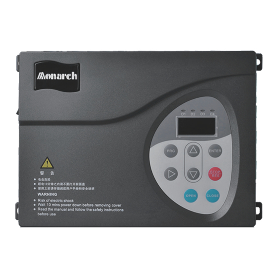
INPUT: 1PH AC220-230V 2.7A 50Hz/60Hz ficates Rated output OUTPUT: 3PH AC0-230V 1.3A 0-99Hz 200W Serial No.: 010150144C700061 Serial No. Suzhou Inovance Technology Co.,Ltd. Manufacturer Made in China 2.2 Structure Figure 2-2 Structure of the NICE900 Logo Operation panel Single-phase power... -
Page 14: Nice900 Models
2.3 NICE900 Models Table 2-1 NICE900 models Power Output Adaptable Input Current Model Input Voltage Capacity Current Motor (kVA) NICE-D-A-S0P2 Single-phase 220 V NICE-D-A-S0P4 (-15% to 20%) NICE-D-A-S0P7 2.4 General Specifications Item Specifications Maximum output 99.00 Hz frequency 1:50 (SVC) - Page 15 Chapter 2 Product Information Item Specifications Indoors Installation Free from direct sunlight, dust, corrosive gas, combustible gas, oil location mist, vapor, drip and salt Lower than 1000 m Altitude Deratedif the altitude is above 1000 m -10°C to +40°C Ambient temperature Derated if ambient temperature is within 45–50°C Humidity...
- Page 16 Mechanical and Electrical Installation...
-
Page 17: Chapter 3 Mechanical And Electrical Installation
Chapter 3 Mechanical and Electrical Installation Chapter 3 Mechanical and Electrical Installation 3.1 Mechanical Installation 3.1.1 Installation Environment Item Requirement Ambient temperature -10°C to 50°C Mount the controller on the surface of incombustible objects with sufficient room for heat dissipation. Heat dissipation Install the controller on the base with screws vertically. - Page 18 Chapter 3 Mechanical and Electrical Installation 3.1.4 Mounting Orientation Use 4 M4x15 screws (with elastic flat washer) with the tightening torque of 1.2 N.m during installation. a) Horizontal installation Figure 3-3 Horizontal installation diagram Fix the four screws b) Vertical installation Figure 3-4 Vertical installation diagram Fix the four screws...
-
Page 19: Electrical Installation
Chapter 3 Mechanical and Electrical Installation 3.2 Electrical Installation 3.2.1 Wiring and Description of Main Circuit Terminals Figure 3-5 Main circuit terminal arrangement Single-phase power input terminals Reserved Controller output terminals Table 3-1 Main circuit terminal description Terminal Name Description Single-phase power input L, N Provide single-phase 220 VAC power supply. - Page 20 Chapter 3 Mechanical and Electrical Installation Table 3-2 Recommended regen. resistor models Controller Model Power of Regen. Resistor (W) Resistance of Regen. Resistor (Ω) NICE-D-A-S0P2 80 W ≥ 250 Ω NICE-D-A-SOP4 80 W ≥ 200 Ω NICE-D-A-SOP7 80 W ≥ 150 Ω...
-
Page 21: Peripheral Electrical Devices
- U, V, W and PE - Encoder 24V, PGA, PGB, PGZ, COM and PE 3.3 Peripheral Electrical Devices 3.3.1 Selection of Peripheral Electrical Devices Controller Model Air Switch (A) Contactor (A) Main Circuit Conducting Cable (mm NICE-D-A-S0P2 NICE-D-A-S0P4 NICE-D-A-S0P7 - 20 -... - Page 22 Chapter 3 Mechanical and Electrical Installation 3.3.2 Description of Peripheral Electrical Devices Electrical Device Mounting Location Function Description It is used to cut off the controller’s power supply Air switch Power input side and provide short circuit protection. • Improve the power factor of the input side. •...
- Page 23 Chapter 3 Mechanical and Electrical Installation - 22 -...
- Page 24 Operation and Trial Running...
-
Page 25: Chapter 4 Operation And Trial Running
Chapter 4 Operation and Trial Running Chapter 4 Operation and Trial Running 4.1 Operation Panel You can modify the parameters, monitor the working status and run or stop the controller by operating the operation panel shown as below: Figure 4-1 Operation panel diagram Function indicator Data display UP key... -
Page 26: Basic Operations
Chapter 4 Operation and Trial Running Name Function Select the displayed parameters in turn in the stop or running state, Shift and select the digit to be modified when modifying parameters. Increase data or function code. Down Decrease data or function code. Door open Open the door in the operation panel operation mode. - Page 27 Chapter 4 Operation and Trial Running Figure 4-3 Example of editing function code If there is a blinking digit, Status parameter press to modify the digit. (default display) 15.00 ENTER F005 F000 F004 ENTER 00.00 ENTER 15.00 To save the setting In Level III menu, if the parameter has no blinking digit, it means that the parameter cannot be modified.
- Page 28 Chapter 4 Operation and Trial Running 4.2.3 Viewing Display at Running or Stop In the stop/running state without fault, you can view the parameters circularly by pressing The parameters to be displayed are set in by setting FA-00 and FA-01. Figure 4-5 Shift between parameters displayed in the running/stop state Shift between parameters Shift between parameters...
-
Page 29: Command Source And Motor Auto-Tuning
Chapter 4 Operation and Trial Running 4.3 Command Source and Motor Auto-tuning 4.3.1 Command Source The NICE900 supports four command sources, as described in the following table. Function Value Description Code Operation panel control It is mainly used in motor auto-tuning. The door machine runs at the frequency set in F0-04. - Page 30 Chapter 4 Operation and Trial Running Door machine manual control (F0-02 = 1) ■ In this mode, the door open/close commands are given by DI terminal. You can allocate the DI terminals with relevant signals in F9-01 to F9-08. For example, connect the door open and close signals respectively to DI5 and DI6, as shown in the following figure.
- Page 31 Chapter 4 Operation and Trial Running Figure 4-8 Motor auto-tuning flowchart (PMSM) Check the mechanical part and encoder signals Perform trial running: F0-02 = 0 (Operation panel control) F0-04 = 5.00 Hz. F1-00 = 1 (PMSM) Press "OPEN" or "CLOSE" to start trial running.
-
Page 32: Door Open/Close Control Mode
Chapter 4 Operation and Trial Running incorrect. You need to replace any two of UVW phases and perform motor auto-tuning again. 5. The identified encoder zero position angle is viewed or modified in F1-14. This parameter must not be modified after motor auto-tuning; otherwise, the controller may not run properly. - Page 33 Chapter 4 Operation and Trial Running 2. Check wiring of the door open/close signals for speed control. The following figure takes Inovance elevator control system to describe wiring of the relevant signals. Figure 4-10 Typical system wiring for speed control...
- Page 34 Chapter 4 Operation and Trial Running 4. Door open/close running curve in speed control Figure 4-11 Door open running curve in speed control Frequency F3-03 F3-00 F3-05 Time Door open command Door open slow-down signal Door open limit signal When the door open command is active, the door machine accelerates to the speed set in F3-00.
- Page 35 The door width pulses need to be identified at first-time running. The controller decelerates and judges door open/close limit based on the door open/close curve. The following figure takes Inovance elevator control system to describe wiring of the relevant signals. Figure 4-13 Typical system wiring for distance control...
- Page 36 Chapter 4 Operation and Trial Running The shield of the encoder cable is grounded on the end connected to the controller (only one end is grounded to prevent interference). 3. Related parameter setting Function Code Parameter Name Value F0-01 Door open/close control mode 1: Distance control F0-02 Command source selection...
- Page 37 Chapter 4 Operation and Trial Running 5. Door open/close running curve in distance control mode Figure 4-15 Door open running curve in distance control mode Frequency F3-03 F3-00 F3-05 Time Door open command F6-04 x door width Door open slow-down pulse F6-05 x door width Door open limit pulse F6-06 x door width...
- Page 38 Chapter 4 Operation and Trial Running When the door close position reaches (F6-09 x door width), the door machine decelerates again to the speed set in F4-07. It is recommended that F6-09 ≥ 96.0%; reduce F6-09 if there is pulse loss during door open/close. Set the threshold for retracting the door vane in F6-20.
- Page 39 Chapter 4 Operation and Trial Running 2. Related parameter setting Function Parameter Setting Description Code Name F4-14 = 2 Upon door close hindered, the controller stops immediately, outputs the door close hindered signal, and does not respond to the door close command within 10s.
- Page 40 Chapter 4 Operation and Trial Running Function Parameter Setting Description Code Name It is used to limit the door close time. If the controller does not receive the door close limit signal within the time, it determines that door close is hindered, and Door close F5-02 0–9999s...
- Page 41 Chapter 4 Operation and Trial Running - 40 -...
- Page 42 Function Code Table...
-
Page 43: Chapter 5 Function Code Table
Chapter 5 Function Code Table Chapter 5 Function Code Table 5.1 Description of Function Codes The NICE900 series door machine controller has a total of 13 groups of function codes, namely, F0 to F9, FA, FF and FP. FX–YZ in this manual indicates the function code whose function code group is "X"... - Page 44 Chapter 5 Function Code Table Group F0: Basic Parameters Group F7: Distance Control Parameters Group F1: Motor Parameters Group F8: Auxiliary Parameters Group F9: Input and Output Function Group F2: Performance Control Parameters Parameters Group F3: Door Open Running Curve Parameters Group FA: Display and Fault Parameters Group F4: Door Close Running Curve Parameters Group FF: Factory Parameters (Reserved) Group F5: Door Open/Close Auxiliary Parameters Group FP: User Parameters Group F6: Distance Control Parameters...
- Page 45 Chapter 5 Function Code Table Function Min. Parameter Name Setting Range Default Property Code Unit Stator phase resistance of Model F1-06 0.00–99.99 Ω 0.01 Ω ★ PMSM dependent Rotor phase resistance of Model F1-07 0.00–99.99 Ω 0.01 Ω ★ asynchronous motor dependent Leakage inductance of Model...
- Page 46 Chapter 5 Function Code Table Function Min. Parameter Name Setting Range Default Property Code Unit F2-08 Slip compensation coefficient 50%–200% 100% ☆ F2-09 Inertia compensation 0–9999 ★ F2-10 Torque boost 0.0%–30.0% 8.0% 0.1% ☆ F2-11 Over-excitation gain 0–200 ☆ 1: Based on pulses F2-12 Initial position judging method 2: Using data of other tested...
- Page 47 Chapter 5 Function Code Table Function Min. Parameter Name Setting Range Default Property Code Unit Door close startup F4-01 0.1–999.9s 1.0s 0.1s ☆ acceleration time Low speed running time for F4-02 door close startup in speed 0.1–999.9s 1.0s 0.1s ☆ control 0.01 F4-03...
- Page 48 Chapter 5 Function Code Table Function Min. Parameter Name Setting Range Default Property Code Unit F5-01 Door open time limit 0–999.9s 30.0s ☆ F5-02 Door close time limit 0–999.9s ☆ F5-03 Low speed running time limit 0–999.9s ☆ Delay of external door open F5-04 0–999.9s 60.0s...
- Page 49 Chapter 5 Function Code Table Function Min. Parameter Name Setting Range Default Property Code Unit Door close steady speed F5-18 0–9999 ms 200 ms 1 ms ★ delay F5-19 Fault braking current 0.1%–150.0% 100% 0.1% ★ Group F6: Distance Control Parameters 0: Disabled Door width auto-tuning F6-00...
- Page 50 Chapter 5 Function Code Table Function Min. Parameter Name Setting Range Default Property Code Unit Pulse at door open limit F6-19 0.0%–99.9% 0.0% 0.1% ☆ output Pulse at door close limit F6-20 0.0%–99.9% 0.0% 0.1% ☆ output F6-21 Door position feedback pulse 0.0%–99.9% 33.0% 0.1% ☆...
- Page 51 Chapter 5 Function Code Table Function Min. Parameter Name Setting Range Default Property Code Unit 0: Invalid F9-01 DI1 function selection 1: Door open command ★ 2: Door close command 3: External reset signal 4: Forbid terminal input F9-02 DI2 function selection ★...
- Page 52 Chapter 5 Function Code Table Function Min. Parameter Name Setting Range Default Property Code Unit Group FA: Display and Fault Parameters FA-00 Display in running state 1–511 ☆ FA-01 Display in stop state 1–63 ☆ FA-02 1st fault type 0–30 ●...
- Page 53 Chapter 5 Function Code Table Function Min. Parameter Name Setting Range Default Property Code Unit Group FF: Factory Parameters (Reserved) FF-00 Reserved ● Group FP: Display and Fault Parameters FP-00 User password 0–9999 ☆ 0: No function 1: Restore the default setting FP-01 Parameter update ★...
- Page 54 Description of Function Codes...
-
Page 55: Chapter 6 Description Of Function Codes
Chapter 6 Description of Function Codes Chapter 6 Description of Function Codes Group F0: Basic Parameters Function Code Parameter Name Setting Range Default Min. Unit F0-00 Control mode 0, 1 • 0: Sensorless vector control (SVC) It applies to common applications except for the permanent magnet synchronous motor (PMSM). - Page 56 Chapter 6 Description of Function Codes • 1: Door machine terminal control Door open/close is controlled by status combination of DI terminals of the controller. DI with Signal "Door Open DI with Signal "Door Close Running State Command" Command" Stop Door close Door open Door open...
-
Page 57: Group F1: Motor Parameters
Chapter 6 Description of Function Codes down switches in the speed control mode (F0-01 = 0). When F0-05 is set to a non-zero value, the NO/NC feature of the corresponding input signals are as follows: F0-05 = 1 F0-05 = 2 F9-01 = 13 (Door close limit NO) F9-01 = 113 (Door close limit NC) F9-02 = 15 (Door close deceleration NO) - Page 58 Chapter 6 Description of Function Codes Function Parameter Name Setting Range Default Min. Unit Code F1-01 Rated motor power 0–750 W Model dependent F1-02 Rated motor voltage 0–250 V 100 V F1-03 Rated motor current 0.001–9.900 A Model dependent 0.001 A F1-04 Rated motor frequency 1.00–99.00 Hz...
- Page 59 Chapter 6 Description of Function Codes Function Code Parameter Name Setting Range Default Min. Unit F1-16 Motor auto-tuning mode 0–4 Note Motor auto-tuning can be performed only in the operation panel control mode (F0-02 = 0). Before motor auto-tuning, set motor ratings (F1-00 to F1-05) and PPR of the encoder (F2-14) correctly. If a PMSM is used, motor auto-tuning is mandatory in one of the following conditions: •...
-
Page 60: Group F2: Performance Control Parameters
Chapter 6 Description of Function Codes - F1-12 (Shaft Q inductance of PMSM) For no-load auto-tuning, the PMSM must be disconnected from the load. If not, F1-14 is not accurate, which affects motor control performance. During auto-tuning, the controller opens or closes the door slowly after receiving the door open/close command, and instructs reverse running after a distance. - Page 61 Chapter 6 Description of Function Codes • F2-00 and F2-01 are PI regulation parameters when the running frequency is smaller than the value of F2-02 (Switchover frequency 1). F2-03 and F2-04 are PI regulation parameters when the running frequency is larger than •...
- Page 62 Chapter 6 Description of Function Codes Function Code Parameter Name Setting Range Default Min. Unit F2-08 Slip compensation coefficient 50%–200% 100% It is used only in CLVC mode. It affects the dynamic performance and load current of the motor and requires no adjustment generally. Function Code Parameter Name Setting Range...
-
Page 63: Group F3: Door Open Running Curve Parameters
Chapter 6 Description of Function Codes Note In the applications where the motor is of small power or the load inertia is small, a large value of this parameter may result in serious motor overshoot or oscillation. Function Code Parameter Name Setting Range Default Min. - Page 64 Chapter 6 Description of Function Codes Figure 6-3 Door open running curve in speed control mode The dotted line part indicates the running curve when F5-06 = 0 (Linear acceleration/deceleration). Frequency F3-03 F3-02 F3-01 F3-04 F3-06 F3-00 F3-05 Time Door open command Door open slow-down signal Door open limit signal...
- Page 65 Chapter 6 Description of Function Codes 2. When the door open position reaches (F6-04 x door width), the door machine accelerates to the speed set in F3-03 within the acceleration time set in F3-04. 3. When the door open position reaches (F6-05 x door width), the door machine decelerates to creep, with the speed =set in F3-05 and deceleration time set in F3-06.
-
Page 66: Group F4: Door Close Running Curve Parameters
Chapter 6 Description of Function Codes Function Code Parameter Name Setting Range Default Min. Unit F3-12 Door open limit low speed 0.00 Hz to F3-03 3 Hz 0.01 Hz It is used to set the target frequency at which the door machine runs when the door open limit signal is received or the pulses reach the door open limit requirement during open. - Page 67 Chapter 6 Description of Function Codes The door close process in speed control is as follows: 1. After the door close command becomes active, the door machine accelerates to the speed set in F4-00 within the acceleration time set in F4-01. 2.
- Page 68 Chapter 6 Description of Function Codes 5. After door vane retraction is completed and the rotor is locked, the door machine enters the torque holding state at the speed set in F4-07 and holding torque set in F4-12. The door width is reset to 0. 6.
- Page 69 Chapter 6 Description of Function Codes It is used to set the door close holding torque after the door close limit is reached. Function Code Parameter Name Setting Range Default Min. Unit Working mode upon door close F4-14 0–3 hindered •...
-
Page 70: Group F5: Door Open/Close Auxiliary Parameters
Chapter 6 Description of Function Codes Figure 6-7 Door close hindered judgment Hinder torque F4-20 Curve 1 F4-19 Running F4-18 F4-17 frequency (Hz) 1. According to the preceding figure, set these parameters according to the requirement: V1 (F4-17) ≥ V2 (F4-18), T1 (F4-19) ≤ T2 (F4-20) 2. - Page 71 Chapter 6 Description of Function Codes It is used to set the maximum running time of low speed door open and close when the low speed running signal is enabled. Set this parameter based on the actual situation. The value must be equal to or greater than the sum of the door open and door close time setting (parameter group of door open and close running curve);...
- Page 72 Chapter 6 Description of Function Codes Function Code Parameter Name Setting Range Default Min. Unit F5-11 Door close curve selection 0, 1 It is used to set the running curve of the door machine during door close. • 0: Linear acceleration/deceleration •...
-
Page 73: Group F6: Distance Control Parameters
Chapter 6 Description of Function Codes Figure 6-8 S curve acceleration/deceleration diagram Frequency F0-04 Acceleration Deceleration Time segment segment T1 stands for F5-07, during which the output frequency change slope (that is, speed change rate) increases gradually. T2 is stands for F5-08, during which the output frequency change slope reduces gradually to low speed frequency. - Page 74 Chapter 6 Description of Function Codes • 0: Disabled • 1: Enabled F6-00 = 1 in the prerequisite of F0-02 = 2. After you press , door width auto-tuning is started. The door machine runs with OPEN CLOSE the close-open-close logic, and stores the door width upon door open limit and locked-rotor. For details on the operation, see Chapter 4.
- Page 75 Chapter 6 Description of Function Codes Function Code Parameter Name Setting Range Default Min. Unit Low speed running distance of door F6-07 0.0%–30.0% 10.0% 0.1% close startup in distance control It records the number of pulses in real time during door close in distance control. When the number of pulses is equal to or less than value (door width x (100% –...
- Page 76 Chapter 6 Description of Function Codes It is used to set the torque upper limit during door width auto-tuning and first power-on running. This parameter is valid only in distance control. For details, see Chapter 4. Function Code Parameter Name Setting Range Default Min.
-
Page 77: Group F7: Demonstration Function Parameters
Chapter 6 Description of Function Codes position feedback signal is output. It is used together with F9-12 (Door position feedback signal output). Group F7: Demonstration Function Parameters Function Code Parameter Name Setting Range Default Min. Unit Door open limit holding time in F7-00 1.0–999.9s 2.0s... -
Page 78: Group F8: Auxiliary Parameters
Chapter 6 Description of Function Codes It is used to set the limit of door open and close times in demonstration mode. When the actual door open and close times in demonstration mode is equal to or greater than F7-03, demonstration running ends automatically. - Page 79 Chapter 6 Description of Function Codes value 9999 hours, the controller starts a new round of counting. Function Code Parameter Name Setting Range Default Min. Unit F8-10 Auxiliary function selection 0–9999 It is used to select the required function. Function Default 1: Trigger door open/close command Bit0...
-
Page 80: Group F9: Input And Output Function Parameters
Chapter 6 Description of Function Codes Function Code Parameter Name Setting Range Default Min. Unit F8-12 Drive function selection 0–9999 Bit0 = 0: Overall 7-segment modulation (reduce the noise) Bit0 = 1: 7-segment/5-segment automatic switchover during running Function Code Parameter Name Setting Range Default Min. - Page 81 Chapter 6 Description of Function Codes • 5: Forbid terminal input during torque holding During torque holding upon door open/close limit, zero torque holding is performed if this signal is active. • 6: Low speed door close command When this signal is active, the door closes at a low speed frequency (F0-06). •...
-
Page 82: Group Fa: Display And Fault Parameters
Chapter 6 Description of Function Codes During door close, the controller outputs this signal after the controller receives the door close limit signal or the counting pulses reach the value for door close limit. 3: Door open limit signal output 1 •... - Page 83 Chapter 6 Description of Function Codes the running state. FA-00 includes 9 binary bits, each defining a parameter. A total of 9 parameters can be can be displayed during running. The 9 binary bits correspond to the running parameters listed in the following table. Parameter Name Default Bit0...
- Page 84 Chapter 6 Description of Function Codes In the running state, the display of FA-00 is a decimal value. You can press to view the parameter indicated by each bit circularly. Figure 6-10 Shift between parameters displayed in the running state Shift between parameters displayed in running state Function Code...
- Page 85 Chapter 6 Description of Function Codes Function Code Parameter Name Setting Range Default Min. Unit FA-11 5th fault prompt 0–9 FA-12 Bus voltage upon latest fault 0–999.9 V 0.1 V FA-13 Output current upon latest fault 0–99.00 A 0.00 A 0.01 A FA-14 Running frequency upon latest fault...
- Page 86 Chapter 6 Description of Function Codes Function Code Parameter Name Setting Range Default Min. Unit FA-19 Input signal display It is used to view the input signal state. When an input signal is active, the corresponding LED is ON. The LEDs are arranged as 1, 2, 3, and 4 from left to right. The meaning of each segment is defined in the following table.
- Page 87 Chapter 6 Description of Function Codes The meaning of each segment is defined in the following table. Segment Segment Segment Meaning Meaning of ON Meaning of ON (LED3 & (LED1) (LED2) of ON LED4) Door open limit signal Door lock signal output 0 output Door close limit signal...
-
Page 88: Group Fp: User Parameters
If FP-00 is set to 00000, the previously set user password is cleared, and the password protection function is disabled. Remember the password that you set. If the password is set incorrectly or forgotten, contact Inovance to replace the control board. Function Code Parameter Name... - Page 89 Chapter 6 Description of Function Codes - 88 -...
- Page 90 Maintenance and Troubleshooting...
-
Page 91: Chapter 7 Maintenance And Troubleshooting
Chapter 7 Maintenance and Troubleshooting Chapter 7 Maintenance and Troubleshooting 7.1 Maintenance 7.1.1 Routine Maintenance The influence of the ambient temperature, humidity, dust and vibration will cause the aging of the components inside the controller, which may cause potential faults or reduce the service life of the controller. -
Page 92: Fault Information And Troubleshooting
7.1.4 Storage of the Controller For storage of the controller, pay attention to the following two aspects: 1. Pack the controller with the original packing box provided by Inovance. 2. Long-term storage degrades the electrolytic capacitor. Thus, the controller must be energized once every 2 years, each time lasting at least 5 hours. - Page 93 Chapter 7 Maintenance and Troubleshooting Fault Description Cause Troubleshooting Remarks Code 1. The main circuit output 1. Eliminate external faults is grounded or short- such as wiring error. Overcurrent circuited. Er02 during 2. Perform motor auto- 2. Motor auto-tuning is acceleration tuning again.
- Page 94 Chapter 7 Maintenance and Troubleshooting Fault Description Cause Troubleshooting Remarks Code 1. The guide rail of the 1. Check the guide rail of elevator door is blocked by System the elevator door. Er10 stuff. overloaded 2. Reduce the load. 2. The load is too heavy. 1.
- Page 95 Chapter 7 Maintenance and Troubleshooting Fault Description Cause Troubleshooting Remarks Code 1. F5-01 (Door open time limit) is smaller than the total door open time. 2. F5-02 (Door close time 1. Set F5-01 to larger than limit) is smaller than the the total door open time.
- Page 96 Chapter 7 Maintenance and Troubleshooting Fault Description Cause Troubleshooting Remarks Code 1. Acceleration or deceleration is too abrupt. 1. Increase the acceleration or 2. The motor angle deceleration time. Speed obtained through auto- Er32 deviation tuning is incorrect, causing 2. Perform angle auto- protection runaway.
-
Page 97: Revision History
Revision History Revision History Date Version Change Description Jan 2015 V0.0 First issue. Dec 2016 Modified product name, designation rule and nameplate. Nov 2018 Updated logo. - 96 -... -
Page 98: Warranty Agreement
3) The maintenance fee is charged according to the latest Maintenance Price List of Inovance. 4) If there is any problem during the service, contact Inovance's agent or Inovance directly. 5) Inovance reserves the rights for explanation of this agreement. - Page 99 //www.inovance.com Shenzhen Inovance Technology Co., Ltd. Add.: Building E, Hongwei Industry Park, Liuxian Road, Baocheng No. 70 Zone, Bao’an District, Shenzhen Tel: +86-755-2979 9595 Fax: +86-755-2961 9897 Service Hotline: 400-777-1260 http: //www.inovance.com Copyright Shenzhen Inovance Technology Co., Ltd.
Need help?
Do you have a question about the NICE-D-A-S0P2 and is the answer not in the manual?
Questions and answers