
Subscribe to Our Youtube Channel
Summary of Contents for Enovation Controls Murphy DF Series
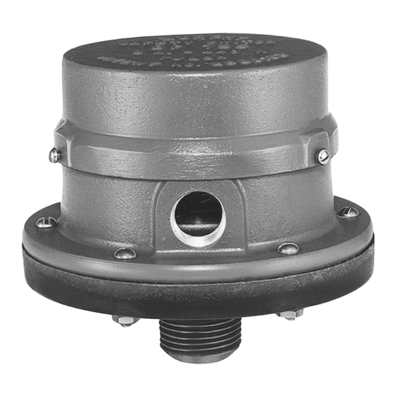
- Page 1 DF Series Hydrostatic Head Level Switches Installation and Operations Manual 00-02-0831 2013-03-21 Section 15 1-800-548-1191 - http://www.partdeal.com - info@partdeal.com...
- Page 2 The latest version of this manual can be found at www.fwmurphy.com. Please read the following information before installing. BEFORE BEGINNING INSTALLATION OF THIS MURPHY PRODUCT: Read and follow all installation instructions. Please contact Enovation Controls immediately if you have any questions. 1-800-548-1191 - http://www.partdeal.com - info@partdeal.com...
-
Page 3: Table Of Contents
Table of Contents Table of Contents ........................iii Introduction ..........................1 Basic Operation ......................1 Typical Applications ........................3 Water Flood Control Systems ..................3 Low Pressure Gas Blanket on Tank ................3 Typical Wiring Diagrams ....................4 Installation of a Volume Air Cell ....................6 Overview ........................6 Specifications .......................... - Page 4 (THIS PAGE INTENTIONALLY LEFT BLANK) 1-800-548-1191 - http://www.partdeal.com - info@partdeal.com...
-
Page 5: Introduction
Introduction The DF series are diaphragm-operated ‘hydrostatic head pressure’ level switches. A pressure sensitive diaphragm operates a snap-switch that can be wired directly to electric pilot circuits to control pumps at pre-determined levels. A typical application is starting and stopping electric driven pump(s) to maintain tank levels. - Page 6 Set Point Adjustment for the DF757 Locate the threaded adjustment shaft and adjustment knobs (see the following drawings). To increase the low-level set point, rotate the lower knob counterclockwise. NOTE: If the adjustment shaft turns when rotating the adjustment knobs, firmly grasp the adjustment shaft with a pair of needle nose pliers, and then rotate the knob.
-
Page 7: Typical Applications
Typical Applications This section covers some general situations where the rugged DF Series switches provide a simple-to-install solution. Applications include: Water Flood Systems Diesel Day Tanks Crude Oil Tanks Sumps Salt Water Disposal Systems Cooling Towers Water Flood Control Systems The diagram below displays eight DF Series switches installed on Raw Water and Clear Water tanks. -
Page 8: Typical Wiring Diagrams
Typical Tank Mounting The following graphics show different methods of mounting DF755 switches in tank applications. Typical Wiring Diagrams Presented as an assist to wiring typical DF Series level switches. Starts at Low Level, Stops at High – Start motor when pre- determined low level is reached and stop when high level is reached. - Page 9 Single Magneto Shutdown – Wiring of magneto to Normally Open (NO) switch terminal shuts engine down at a pre-determined high level (Shown at right). Wire to Normally Closed (NC) terminal to shutdown on low level. Dual Magneto Shutdown – Shutdown dual magneto engines using a Murphy MS2120 Magnetic Switch.
-
Page 10: Installation Of A Volume Air Cell
The pump is held in a standby condition. An air purge may be required in the sensor line. For additional information, consult Enovation Controls. Choosing a Volume Cell The volume cell should be constructed of material which will be unaffected by the liquid being measured. - Page 11 Installation of the Volume Cell Install the volume cell with reference to the level at which you wish the pump to start and stop. Secure the volume cell with a substantial bracket that will not allow the cell to float or tilt when the water level rises.
-
Page 12: Specifications
Specifications Snap-switch Ratings SPDT (standard–all models) 5 A @ 125, 250, or 480 VAC • 1/2 A @ 125 VDC, 1/4 A @ 250 VDC • DPDT (optional) 10 A @ 28 VDC • 10 A @ 120, 230 VAC •... -
Page 13: Service Parts
Service Parts DF755 Description Part Number Cover (aluminum) 15050081 Case (aluminum) 15050082 Cover Screws (3), #6–32 x 5/16 round head 80040607 SPDT snap-switch and movement assembly/repair kit (5 amp) 15000122 Screws (3) for switch assembly to case, #6–32 x 1/4 round head 80040605 Diaphragm repair kit 15000123... - Page 14 (THIS PAGE INTENTIONALLY LEFT BLANK) 1-800-548-1191 - http://www.partdeal.com - info@partdeal.com...
- Page 15 (THIS PAGE INTENTIONALLY LEFT BLANK) 1-800-548-1191 - http://www.partdeal.com - info@partdeal.com...
- Page 16 1-800-548-1191 - http://www.partdeal.com - info@partdeal.com...
Need help?
Do you have a question about the Murphy DF Series and is the answer not in the manual?
Questions and answers