Table of Contents
Advertisement
Quick Links
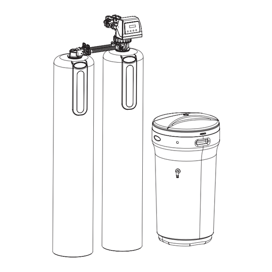
485 SIMTAN CONDITIONER
Iron, Manganese & Tannin Removal
1. Page 21 of this manual contains important maintenance procedures for the continued proper
operation of your unit. These MUST be performed regularly for your warranty to remain valid.
2. Read all instructions carefully before operation.
3. Avoid pinched o-rings during installation by applying NSF certified lubricant to all seals (provided with install kit).
4. This system is not intended for treating water that is microbiologically unsafe or of unknown quality without
adequate disinfection before or after the system.
Canada West
Canada East
855 Park St.
490 Pinebush Rd.
Unit 1
Unit 1
Regina, SK S4N 6M1
Cambridge, ON N1T 0A5
U.S.A.
56 Lightcap Rd.
9760 Mayflower Park Drive,
Pottstown, PA 19464
Suite 110
Carmel, IN 46032
4645 McDowell Rd. W
Suite 106
Phoenix, AZ 85035
Advertisement
Table of Contents

Related Manuals for NOVO WATER 485 SIMTAN

Summary of Contents for NOVO WATER 485 SIMTAN
- Page 1 485 SIMTAN CONDITIONER Iron, Manganese & Tannin Removal 1. Page 21 of this manual contains important maintenance procedures for the continued proper operation of your unit. These MUST be performed regularly for your warranty to remain valid. 2. Read all instructions carefully before operation.
-
Page 2: Table Of Contents
READ THIS PAGE FIRST BEFORE STARTING INSTALLATION HOW YOUR WATER CONDITIONER WORKS COMPONENTS & SPECIFICATIONS SPECIFICATION SYSTEM DIMENSIONS BRINE TANK DIMENSIONS INSTALLATION UNPACKING / INSPECTION ASSEMBLING BRINE TANK CHECK VALVE TYPE AND VALVE SERIAL # BEFORE INSTALLATION PREPARATIONS INSTALLATION STEPS INSTALLATION OPERATION STARTUP &... -
Page 3: Read This Page First
READ THIS PAGE FIRST BEFORE STARTING INSTALLATION Read this manual thoroughly to become familiar with the Avoid pinched o-rings during installation by applying appliance and its capabilities before installing or operating (provided with install kit) NSF certified lubricant to all seals. the new appliance. -
Page 4: How Your Water Conditioner Works
HOW YOUR WATER CONDITIONER WORKS SIMTAN conditioners remove hardness, iron, manganese and tannin in the water by an ion exchange process. They remove ions such as calcium, magnesium, iron and manganese in the water by trading it for sodium ions producing soft water. The tannin in the water is exchanged similarly through an exchange process exchanging the Tannin for Chloride ions in the water. -
Page 5: Specification
SPECIFICATION Working Temperature: This unit must be Specifications 485SIMTAN-100 485SIMTAN-150 485SIMTAN-200 485SIMTAN-300 operated at temperatures between 40°F and Purolite 850 Models* 15010480-1 15010481-1 15010482-1 15010483-1 110°F (4°C - 43°C). Working Pressure: This water conditioner Purolite 860 Models* 15011480-1 15011481-1 15011482-1 15011483-1 must be operated on pressures Factory Settings - High Capacity... -
Page 6: Brine Tank Dimensions
BRINE TANK DIMENSIONS Tank Dimensions Liquid Volume Salt Capacity (inches) Model US Gal Liters L x W x H Brine Tanks BTR-100 29.5 111.5 18.1 x 34.7 270.0 122.2 BTR-145 42.3 159.7 20.3 x 37.4 385.0 174.2 BTR-200 53.0 200.3 23.0 x 40.5 700.0 316.7... -
Page 7: Unpacking / Inspection
UNPACKING / INSPECTION Be sure to check the entire unit for any shipping damage or parts loss. Also note damage to the shipping cartons. Contact the transportation company for all damage and loss claims. The manufacturer is not responsible for damages in transit. Small parts, needed to install the conditioner, are in a parts box. - Page 8 For SIMTAN-300 model, the media and Control Valve is packaged separately in carton and bags What is included with SIMTAN-300 model? There are 8 Red clips. 1. Tank c/w Adaptor Please check to make 2. Tank c/w Parallel Adaptor sure you have all of 3.
-
Page 9: Assembling Brine Tank
Make sure the bypass is attached well to the control valve. Pipe connector - 14” - 18” / 8” - 12” Tanks x 2 Connect the straight or elbow connectors to the bypass with red clips. Connect the inlet and outlet of the water conditioner to the plumbing of the house. -
Page 10: Check Valve Type And Valve Serial
CHECK VALVE TYPE AND VALVE SERIAL # Check to make sure Valve Type is Upflow (UF) (left Sticker shown below). The right Sticker shows the serial # of the control valve. The middle Sticker is dataplate which provides information of Serial # and Date of Manufacture of complete system. Both Serial # labels are important for troubleshooting. Please record these numbers for future use on page 20 in the maintenance section. -
Page 11: Before Installation
BEFORE INSTALLATION NOTE Make sure you have a copy of your most recent water test results. If your water has not been tested previously you can contact All government codes and your supplier of this product to obtain a water sample bottle to be sent to one of our facilities for a free analysis. It is important regulations governing the that this product not be installed until you have this information. -
Page 12: Preparations
PREPARATIONS 1. Media Installation (When Necessary). Models larger than 2.0 CF of media are shipped with separate media in pails or boxes. All other model sizes come pre-loaded from the factory and this step is not required upon installation. Plug the Riser Tube The riser (distributor) -
Page 13: Installation Steps
PREPARATIONS Planning Your Installation Select the location of your conditioner tank with care. Various conditions which contribute to proper location are as follows: 1. All installation procedures must conform to local and state or provincial plumbing codes. 2. Outside faucets used to water lawns and gardens should not supply untreated water, replace untreated water with feed water to the unit. If necessary to do this please install check valve, see page 15. - Page 14 INSTALLATION STEPS Using the Allen Key (included), place the unit in the bypass position. Slowly turn on the main water supply. At the nearest cold treated water tap nearby remove the faucet screen, open the faucet and let water run a few minutes or until the system is free of any air or foreign material resulting from the plumbing work. *Automatic Water Bypass The regeneration cycle lasts approximately 1.5 hours to 3.0 hours depending on the specific model, after which treated water service will be restored.
-
Page 15: Installation
INSTALLATION Cold (Raw Water Inlet) Cold (Treated Water) To Outside Faucet *Check Valve (Optional) Water Conditioner Cold (Treated Water Outlet ) *NOTE Hot (Treated Water Outlet) Water Heater Check local plumbing codes in regards to requirements for use of Check Valve or Inlet back flow prevention or vacuum breaker... -
Page 16: Startup & Programming
STARTUP & PROGRAMMING STEP 1. Connect the Transformer to the Valve Plug the 12-volt transformer into a 120 VAC 60 Hz outlet. The control valve is controlled with simple, user-friendly electronics displayed on an LCD screen. When power is connected, the screen will show the following Key Pad Configuration information in sequence: 1. - Page 17 STARTUP & PROGRAMMING (CONTINUED) Level 1 PROGRAMMING: PRESS SETTINGS KEY AUG/30/2019 TIME OF DAY 3 SEC TO UNLOCK 12:15AM 12:15AM 1. The display will read “PRESS SETTINGS 3. Press SETTINGS 4. Now press UP or DOWN until you hear 3 SEC TO UNLOCK”. beep.
- Page 18 STARTUP & PROGRAMMING (CONTINUED) Level 1 PROGRAMMING: - CONTINUED SET HARDNESS SET HARDNESS GRAINS GRAINS 12. Now press UP 14. Now press UP or DOWN 13. Press SETTINGS once to DOWN key to change key to change HARDNESS value. highlight value. the DAY value to desired day.
- Page 19 STARTUP & PROGRAMMING (CONTINUED) REGEN. TIME PROGRAMING REGEN. TIME 05:00 PM COMPLETE 02:00 AM 21. Press SETTINGS 21. Press SETTINGS once to once to 22. Now press UP highlight value. COMPLETE PROGRAMING. DOWN keys to change REGEN. TIME. SETTING VACATION MODE This function may be activated during a prolonged absence, such as a vacation for more than 2 weeks.
-
Page 20: Plumbing System Clean-Up
STARTUP & PROGRAMMING (CONTINUED) Start up and *Add Salt to the Brine Tank Put 40 kgs of crystal water conditioner salt in the programming brine tank. The unit will automatically fill the water to the correct level when it regenerates. complete. -
Page 21: Maintenance Instructions And Schedule
MAINTENANCE INSTRUCTIONS AND SCHEDULE Service Schedule Ÿ The seals and spacers along with the piston assembly should be inspected/cleaned or replaced every year depending on the inlet water quality and water usage. See inspection and replacement of Piston assembly and seal and spacer kit, page 21, figure 2. Ÿ... -
Page 22: Res-Up® Feeder Installation Instructions (Optional)
MAINTENANCE INSTRUCTIONS AND SCHEDULE Care of Your Conditioner To retain the attractive appearance of your new water conditioner , clean occasionally with a mild soap solution. Do not use abrasive cleaners, ammonia or solvents. Never subject your conditioner to freezing or to temperatures above 43°C (110°F). Resin Cleaner An approved resin cleaner MUST be used on a regular basis if your water supply contains iron. - Page 23 RES-UP FEEDER INSTALLATION INSTRUCTIONS ® (OPTIONAL) 4. IInstall the holder and the Res Care Solution 5. Take off the small hole cover on the Brine Well lid. 6. Take off the cover of the Res care bottle . Insert the wick, making sure it touches the bottom of the bottle.
-
Page 24: Trouble Shooting Guide
TROUBLE SHOOTING GUIDE Problem Possible Solutions 1. CONDITIONER DELIVERS UNTREATED WATER A. Close bypass valve A. Bypass valve is open B. Add salt to brine tank and maintain salt level above water level B. No salt in brine tank C. Replace injectors and screen C. -
Page 25: Replacement
INSPECTION AND REPLACEMENT OF PISTON ASSEMBLY AND SEAL AND SPACER KIT Piston Fig. 2 Assembly Seal and Spacer Remove 3 X Plate Screws Brine Valve Assembly 1. Follow steps 1 to 6 of timer /Powerhead 3. Remove the plate from the valve body and pull the 5. -
Page 26: Servicing Of Parallel Adaptor
SERVICING OF PARALLEL ADAPTOR Tank and Valve Connection Parts NOTE A. Tank adaptor w/ O ring Full disassembly requires B. Pipe connector - 8” - 12” Tanks specialty wrenches item’s Pipe connector - 14” - 18” Tanks 60010116 and 60010117 and C. -
Page 27: Replace Meter Assembly
THE FOLLOWING ‘REPLACEMENT SECTION’ , PAGES 26 TO 29 CONTAIN CONTENT THAT SHOULD ONLY BE USED BY A QUALIFIED SERVICE TECHNICIAN: REPLACE METER ASSEMBLY Meter Cable 1. Disconnect the meter cable from the meter. 2. Disconnect the valve from bypass by removing clips 3. -
Page 28: Replacing The Bypass And Meter Cable
REPLACING THE BYPASS AND METER CABLE If valve is manufactured before March 20th, 2018, and customer wishes to replace or service impeller on bypass. Customer can order 60010238. If customer wishes to replace to new design, then follow the steps below. Grey Meter Cable 60010267 Bypass comes with Meter... -
Page 29: Replace Drain Line Flow Control
REPLACE DRAIN LINE FLOW CONTROL Drain Line Elbow Clip 1. Pull the drain line clip and remove the drain line elbow and washer 2. Clean/replace drain line washer Drain washer NOTE Be sure to shut off any bypass line. REPLACE BRINE LINE FLOW CONTROL Brine Line Elbow Clip REPLACING PCBS... -
Page 30: Display Replacement
DISPLAY REPLACEMENT Remove Display by removing the screws shown in the picture AFTER SERVICING 1. Reconnect drain line 2. Return bypass or inlet valve to normal in service position. Water Pressure will automatically build in the conditioner 3. Check for leaks at all sealed areas. Check Drain seal with the control in the backwash position 4. -
Page 31: Regeneration Process Explained
REGENERATION PROCESS EXPLAINED 1. Backwash: During the backwash cycle, water enters A850/A860 RESIN tank through the center of the distribution tube and flows upwards in A850/A860 RESIN tank expanding the media bed and carrying any precipitated contaminents trapped within the bed. It then travels to SST60 RESIN tank through the center of the distribution tube and flows upwards in SST60 RESIN tank and then out to the drain. -
Page 32: Parts Breakdown
PARTS BREAKDOWN Part # 60010012S Part # Control Valve 60010068M 3/4” Elbow Adapters Media: A850 Media: SST60 A860 RESIN RESIN 1” Straight Adapters Bypass - Part # 60095101 Parallel Tank Adaptor W/ Oring Part #60010012S Tank Adaptor W/Oring Part # 60010068M SST60 RESIN TANK Model... -
Page 33: Powerhead
PARTS BREAKDOWN Part # Description (Water group) 60010115 Meter Assembly B15* 60010178 485HE Main Pcb(Upflow) 60010179 485HE Main Pcb(Downflow) 60010575 Screw-4.2×12 60010661 Washer-4x12 60010661 Magnet(3×2.7) Powerhead Parts List B11* 60095095 BNT85HE Brine Gear(Upflow) Part # Description 92392 BNT85HE Brine Gear(Downflow) (Water group) 60095077 BNT85 Mounting... -
Page 34: Bypass
PARTS BREAKDOWN Bypass Parts List Part # Part # Description (Water Group) (Canature) Part # Part # Description 92846 05056155N Plug Clip (Water Group) (Canature) 60095090 21709004B Shaft Clip 60010006 70020007 Bypass Tool 60010209 05056146 Bypass Plug 05056212 063 Bypass Body Straight 1”... -
Page 35: Valve Body
PARTS BREAKDOWN Valve Body Parts List Part # Description (WaterGroup) 60010075 Screw-M5x12(Hexagon) Part # Part # Description Description 60010076 Screw-M5x16(Hexagon With Washer) (WaterGroup) (WaterGroup) End Plug Retainer 60010190 O-Ring-¢32×3 BLFC(optional) BNT85HE Rod 60010189 O-Ring-¢18×3 60010188 O-Ring-¢8×1 Piston Pin 60010174 Injector Plug Body 60010172 BNT85HE Brine Line Elbow BNT85HE Quad Ring Plug Cover... -
Page 36: Tank And Valve Connection
PARTS BREAKDOWN Tank and Valve Connection Part #s Part # Part Description 60010068M TANK ADAPTOR W/ O RING 80127819 PIPE CONNECTOR - 8” - 12” TANKS 80127817 PIPE CONNECTOR - 14” - 18” TANKS 60010012S PARALLEL TANK CONNECTOR W/ O RING 60010025 RED CLIPS (4PCS) 60010016... -
Page 37: Level 2 Programming (Optional Settings)
LEVEL 2 PROGRAMMING (OPTIONAL SETTINGS): NOTE CAUTION: DO NOT CHANGE LEVEL 2 SETTINGS WITHOUT CONSULTING Under normal use there A CANATURE WATERGROUP TECHNICIAN (1-877-288-9888). Wrongly is no need to change the settings under level 2 changing the settings can result in malfunction of the unit. programming. -
Page 38: Master Programming Guide
MASTER PROGRAMMING GUIDE 85HE UPFLOW HIMTLC - SIMTAN Programming MASTER SETTINGS PRESS & HOLD UNIT SIZE UF FLOW VALVE TYPE UF FLOW UF FLOW UF FLOW SOFTWARE VER. S1.4 or higher S1.4 or higher S1.4 or higher S1.4 or higher METER RATIO AFTER MAR 20,2018 5.68 5.68... -
Page 39: Important Warranty And Maintenance Information
IMPORTANT WARRANTY AND MAINTENANCE INFORMATION Please have the information below filled out and available when calling in for parts or warranty: Model number: Serial number: Valve Serial number: Date installed: Additional notes: ___________________________________________________________________ ___________________________________________________________________ ___________________________________________________________________ ___________________________________________________________________ ___________________________________________________________________ ___________________________________________________________________... - Page 40 TOLL FREE: 1-877-288-9888 • • • • Regina, SK Cambridge, ON Carmel, IN Pottstown, PA Phoenix, AZ 80150344-1 03/19...
Need help?
Do you have a question about the 485 SIMTAN and is the answer not in the manual?
Questions and answers