Table of Contents
Advertisement
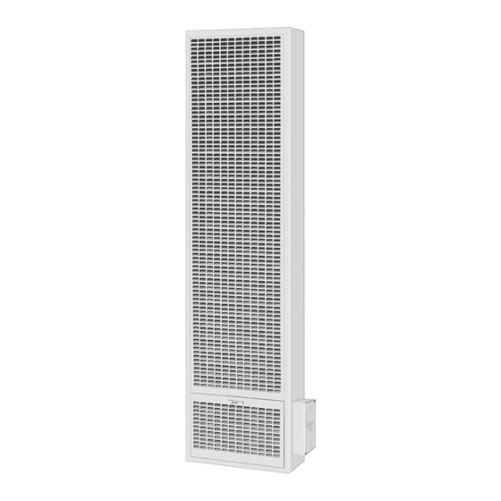
NATURAL GAS - W255GPPR, W255GPPD, W355GPPR, W355GPPD, W505GPPR & W505GPPD
!
WARNING: If the information in these instructions is not
followed exactly, a fire or explosion may result causing property
damage, personal injury or loss of life.
— Do not store or use gasoline or other flammable vapors and
liquids in the vicinity of this or any other appliance.
— WHAT TO DO IF YOU SMELL GAS
• Do not try to light any appliance.
• Do not touch any electrical switch; do not use any phone
in your building.
• Immediately call your gas supplier from a neighbor's phone.
Follow the gas supplier's instructions.
• If you cannot reach your gas supplier, call the fire department.
— Installation and service must be performed by a qualified
installer, service agency or the gas supplier.
INSTALLER: Leave this manual with the appliance.
CONSUMER: Retain this manual for future reference.
- Installation, maintenance, service, troubleshooting & repairs must be performed by a qualified service agency. DO NOT attempt
any of these procedures if you are not qualified as this could expose you to property damage, personal injury, or loss of life and
will invalidate all warranties.
- This unit is for residential use only and is not approved for installation in mobile homes, greenhouses, or environments involving
dusty, wet, corrosive, or explosive conditions. Such conditions will invalidate the warranty and may create unsafe conditions.
- This appliance is equipped with a blocked flue switch designed to protect against a blocked flue condition.
WARNING: Operation of this furnace without the properly installed, factory furnished vent system & vent cap could result in Carbon
Monoxide (C.O.) poisoning and possible death. For your safety, this furnace & the vent system should be inspected at least annually
by a qualified service technician.
Cozy Heating Systems, LLC | cozyheaters.com | 855-589-5380 | 3230 Industrial Pkwy | Jeffersonville, IN 47130
Installation and Operating Instructions
GAS-FIRED VENTED
WALL FURNACE
Page 1
The coating selected to provide
longer life to the heat exchanger
may smoke slightly upon initial
firing. Please provide adequate
ventilation if this occurs.
This unit is NOT to be installed
in mobile homes.
1018454-D
Advertisement
Chapters
Table of Contents

Related Manuals for COZY W255GPPR


Summary of Contents for COZY W255GPPR
- Page 1 Monoxide (C.O.) poisoning and possible death. For your safety, this furnace & the vent system should be inspected at least annually by a qualified service technician. Cozy Heating Systems, LLC | cozyheaters.com | 855-589-5380 | 3230 Industrial Pkwy | Jeffersonville, IN 47130 Page 1...
-
Page 2: Table Of Contents
CONTENTS READ CAREFULLY BEFORE INSTALLING UNIT Before Installation These installation instructions are a general guide and do not supersede applicable local codes and ordinances. Before planning Standards ........... 2 or making the installation be sure it complies with all phases of the Specifications ........ -
Page 3: Specifications
Before installing the wall furnace check the rating plate to verify that the Model Number is correct and that the wall furnace is equipped for the type gas you intend to use. SINGLE WALL FURNACES DOUBLE WALL FURNACES W255GPPR W355GPPR W505GPPR MODEL NUMBERS:... -
Page 4: Introduction
INTRODUCTION This is a gas-fired, gravity vented wall furnace that will operate safely and provide an efficient source of heat when installed, operated and maintained as recommended in these installation and operating instructions. Read these instructions thoroughly before installing, servicing, or using the appliance. If you do not understand any part of these instructions, consult local authorities, other qualified installers, service technician, the gas supplier or the manufacturer. -
Page 5: Clearances
Model 0’ - 2,000’ - 4,000’ - 6,000’ - 8,000’ - 2,000’ 4,000’ 6,000’ 8,000’ 10,000’ W255GPPR W255GPPD W355GPPR W355GPPD ORDER KIT #49820 45-1 High Altitude Kit Model 0’ - 2,000’ - 4,000’ - 6,000’ - 8,000’ - 2,000’... -
Page 6: Combustion & Venting
COMBUSTION AND VENTILATION AIR When installed, this gas appliance must be provided with fresh air for combustion, ventilation, and dilution of hot flue gases. The minimum required volume of the area where the appliance is installed should be 50 cubic feet per 1,000 btu/hr. If installed in an area of the home that is considered an unconfined space, the natural infiltration of air around windows and doors will be adequate. - Page 7 VENTING This appliance must be properly connected to a venting system. FIG. 2 USING ADJACENT Consult local ordinances governing venting. Install only UL listed type STUD SPACE FOR ALL BW 4” oval gas vent. When the vent enters the attic, a listed type B-1 COMBUSTION AIR FROM OUTSIDE round flue pipe may be used.
-
Page 8: Installation
ROUGH-IN INSTRUCTIONS WARNING: Do not bypass the blocked flue switch. To do so could expose the consumer to property damage, personal injury or possible death. NOTE: MAXIMUM WALL THICKNESS FOR A DUAL WALL (W505GPPR, W505GPPD) INSTALLATION IS 5-3/8”. STEP 1. FIG. 3 Attach the base plate (purchased with the vent pipe) to the Height above any More than 10’ header plate using two No. 8 sheet-metal screws through roof surface within 10’... - Page 9 ROUGH-IN INSTRUCTIONS STEP 2. FIG. 7-A Cut out an opening between the studs of 14-3/8” x Rough-In 66-1/2” above the floor plate. Embed the rear flange of Dimensions the channel on top of header into either the drywall or the plastered wall. This provides part of the required fire stop. Square up and nail the header in place with the top front of header located 65-3/4”...
-
Page 10: Thermostat
ROUGH-IN INSTRUCTIONS STEP 6. FIG. 7-E: Vent Installation WARNING: Failure to locate the thermostat properly or to wire the furnace Listed Vent Top correctly may result in continuous 2’ Min. Storm Collar operation, control damage or failure to Roof Flashing operate. This can cause property damage, personal injury, or loss of life. -
Page 11: Installation
INSTALLATION STEP 10. - Remove the door from the heater housing. - Locate the Pilot Pro in the carton and remove the cover from baseplate with a screwdriver. - The Pilot Pro may be installed near the base of either side of the heater housing. - Page 12 INSTALLATION STEP 11. With a phillips-head screwdriver, attach the controls assembly to the side of the heater using: - x3 Screws #8-32 x 3/4” (34) - x3 Nuts #8 (36) DO NOT use a powered drill for this step, it could crack the mounting plate.
- Page 13 INSTALLATION STEP 13. Direct the control module wires (29) through the small notch on the side of the mounting plate (30). Tuck the wires around the edge of the heater housing, against the wall, and inside the heater. On the inside of the heater, you will see orange and black wires extending from the burner.
-
Page 14: Electrical Connection
ELECTRICAL CONNECTION WARNING: Please Use Caution While Installing the Electrical Connection STEP 1. Plug the orange wire from Ignitor (40) into the port labeled "I" on the control module (29). Ensure it is firmly seated. STEP 2. Plug the black flame sensor wire (42) into the port labeled "S"... - Page 15 ELECTRICAL CONNECTION WARNING: Please Use Caution While Installing the Electrical Connection STEP 3. Run a cable tie (48) through the small hole beside the notch on the mounting plate (30). Gather all the wires from the control module (29) with the cable tie (48). Guide any excess wire length back into the heater.
- Page 16 ELECTRICAL CONNECTION WARNING: Please Use Caution While Installing the Electrical Connection STEP 5. A. Connect bare brown SWI wire from the control module wiring harness (38) to the white thermostat wire. B. Connect the brown male blade quick connect SWI wire from the control module wiring harness (38) to the blue female quick connect from safety switch.
-
Page 17: Assembly
ELECTRICAL CONNECTION WARNING: Please Use Caution While Installing the Electrical Connection CAUTION: Label all wires prior to disconnection when servicing controls. Wiring errors can cause improper and dangerous operation. Verify proper operation after servicing and secure wires away from sharp edges, flames or hot surfaces inside and outside the unit. - Page 18 ELECTRICAL CONNECTION WARNING: Please Use Caution While Installing the Electrical Connection FOLLOW THIS STEP IF THE PILOT PRO IS ON THE RIGHT SIDE OF THE HOUSING. (Proceed to step 7-B if the Pilot Pro is on the left side of the housing). Make certain wiring connections are tight before proceeding and secure so they will not be able to contact high temperature locations.
- Page 19 ELECTRICAL CONNECTION WARNING: Please Use Caution While Installing the Electrical Connection FOLLOW THIS STEP IF THE PILOT PRO IS ON THE LEFT SIDE OF THE HOUSING. (Go back to step 7-A if the Pilot Pro is on the right side of the housing). Make certain wiring connections are tight before proceeding and secured so they will not be able to contact high temperature locations.
-
Page 20: Starting Pilot Pro System
STARTING PILOT PRO SYSTEM PER ANSI Z21.71 STEP 1. Turn on all gas and electricity to the appliance. Conduct a gas leakage test of the appliance piping & control system downstream of the shutoff valve in the supply line to the appliance. STEP 2. Adjust thermostat to lowest setting. Place two D Batteries (46) in the Battery pack (28). Initial startup of the pilot pro system may take several minutes due to air in the PILOT gas line. 2b. - Page 21 STARTING PILOT PRO SYSTEM PER ANSI Z21.71 STEP 3. Ensure Ignitor sparks only against the hood of the pilot. Ignitor should not spark against the flame sensor, brackets, heating chamber, burner, etc. Adjust ignitor probe location if required. - DO NOT twist ignitor wire or break from ceramic base. - DO NOT use a broken ignitor. STEP 4. Determine that the pilot is igniting and burning properly and that main burner ignition is satisfactory by turning the thermostat off and back on.
- Page 22 STARTING PILOT PRO SYSTEM PER ANSI Z21.71 STEP 6. Slide the Pilot Pro cover (31) over the controls. Secure in place with: x2 Screw with knob (33) NOTE: Hand-tighten only. Do not over tighten. STEP 7. WARNING: CARBON MONOXIDE POISONING HAZARD Failure to follow the steps outlined below for each appliance connected to the venting system being placed into operation could result in carbon monoxide poisoning or death. The following steps shall be followed for each appliance connected to the venting system being placed into operation, while all other appliances connected to the venting system are not in operation: 1.
-
Page 23: Lighting Instructions
LIGHTING INSTRUCTIONS - ( IID PILOT ) MODELS: W255GPPR W255GPPD W355GPPR W355GPPD W505GPPR W505GPPD Page 23 1018454-D... -
Page 24: Maintenance Instructions
MAINTENANCE INSTRUCTIONS STEP 1. Installation and repair must be done by a qualified service person. The appliance should be inspected before use and at least annually by a professional service person. More frequent cleaning may be required due to excessive lint from carpeting, bedding material, etc. It is imperative that control compartments, burners, pilot burners, circulating air passageways and venting systems of the appliance be kept clean. -
Page 25: Burner Flame Adjustment
BURNER FLAME ADJUSTMENT IID PILOT LADDER SCHEMATIC ( Stainless Steel Burner ) W255GPPR, W255GPPD, W355GPPR, W355GPPD, W505GPPR & W505GPPD FIG. 11 THERMOSTAT SHUTTER 1. FLAME TOO SOFT Yellow Flame. Open air shutters until yellow tipping disappears. MANUAL RESET IGNITION MODULE 2. FLAME... - Page 26 40542-A REAR REGISTER KIT (Optional Accessory) Installation Instructions for Gravity Vented Wall Furnaces STEP 1. Cut hole within stud space behind heater in the back wall 8-1/4” high by 12-5/8” wide. The lower edge of the hole to be 45-3/4” above the floor plate or 47” from the floor (with standard 2”x4” floor base) as shown in Figure 12-A (below).
- Page 27 40542-A REAR REGISTER KIT ( OPTIONAL ACCESSORY ) - Continued Installation Instructions for Gravity Vented Wall Furnaces FIG. 13-A FIG. 13-C INNER PANEL PLASTER DAMPER GROUND FRAME OPEN POSITION CLOSED POSITION CASING REAR FINISHED REGISTER WALL GRILLE 2” X 4” UPRIGHT FIG.
-
Page 28: Wff81-C Fan Kit
MODEL WFF81-C OPTIONAL FAN KIT - (Optional) Installation Instructions FIG. 13 NOTE: This fan kit is to be installed after installation WIRING of the wall furnace and with the wall furnace front DIAGRAM panel in place. JUNCTION STEP 1. This appliance, when installed, must be electrically grounded in accordance with local codes, or in the absence of local codes, with the latest edition of the National Electric Code, ANSI/NFPA No. -
Page 29: Troubleshooting Charts
TROUBLESHOOTING W255GPPR, W255GPPD, W355GPPR, W355GPPD, W505GPPR & W505GPPD Cozy Heating Systems, LLC | cozyheaters.com | 855-589-5380 | 3230 Industrial Pkwy | Jeffersonville, IN 47130 Page 29 1018454-D... - Page 30 TROUBLESHOOTING CHART ( FOR QUALIFIED SERVICE TECHNICIAN ) MAIN BURNER Please follow the following corrective actions in order. SYMPTOM POSSIBLE CAUSES CORRECTIVE ACTION Flame Too 1. Defective operator section 1. Replace complete valve. Large of gas valve. 2. Burner orifice too large. 2. Check with local gas company for proper orifice size & replace. 3.
-
Page 31: Parts
TROUBLESHOOTING CHART ( FOR QUALIFIED SERVICE TECHNICIAN ) MAIN BURNER Please follow the following corrective actions in order. SYMPTOM POSSIBLE CAUSES CORRECTIVE ACTION Failure to 1. Main gas off. 1. Open all manual gas valves. Ignite 2. Defective gas valve. 2. Replace gas valve. 3. Defective pilot assembly. 3. - Page 32 TROUBLESHOOTING CHART ( FOR QUALIFIED SERVICE TECHNICIAN ) BLOCKED FLUE SWITCH Please follow the following corrective actions in order. POSSIBLE CAUSES CORRECTIVE ACTION A. Check vent pipe for blockage, such as bird nest, wasp nest, twigs, leaves, etc. Blockage in Vent Pipe B. Check inside the bottom of the vent pipe to make sure the top of the draft diverter did not rip the inner liner causing it to block part of the vent opening.
-
Page 33: Parts Part List
PARTS LIST W255GPPR, W255GPPD, W355GPPR, W355GPPD, W505GPPR & W505GPPD Cozy Heating Systems, LLC | cozyheaters.com | 855-589-5380 | 3230 Industrial Pkwy | Jeffersonville, IN 47130 Page 33 1018454-D... -
Page 34: Any Component
PARTS LIST - ( GRAVITY WALL FURNACE ) SINGLE WALL FURNACE PARTS DUAL WALL FURNACE PARTS Natural Gas: Natural Gas: W255GPPR, W255GPPD, W505GPPR & W505GPPD W355GPPR & W355GPPD THERMOSTAT: THERMOSTAT: BURNER BURNER ASSEMBLY: ASSEMBLY: When ordering When ordering any component... -
Page 35: Parts
PARTS LIST - ( GRAVITY WALL FURNACE ) ATTN: Contractors and Qualified Service Technicians: We only sell parts through our wholesalers. For prompt parts service, contact the wholesaler from which you purchased your Cozy heater. W255GPPR W355GPPR W505GPPR W255GPPD W355GPPD W505GPPD Model Numbers ...... -
Page 36: Parts
PARTS LIST - ( GRAVITY WALL FURNACE ) Gravity Wall Furnace IID: IID Pilot Assembly: NOTE: Parts & schematic drawings on current models are shown at: cozyheaters.com | Specifications subject to change without notice. 1018454-D Page 36... -
Page 37: Parts
PARTS LIST - ( GRAVITY WALL FURNACE ) ATTN: Contractors and Qualified Service Technicians: We only sell parts through our wholesalers. For prompt parts service, contact the wholesaler from which you purchased your Cozy heater. W255GPPR, W255GPPD, W355GPPR, W355GPPD, W505GPPR and W505GPPD Model Numbers ........ -
Page 38: 40542-A Rear Register Kit
PARTS LIST - ( OPTIONAL KITS ) FSK-A WFF81-C FAN KIT Free Standing Kit Used on Single & Double Wall Models 40542-A REAR REGISTER KIT Used on Single Wall Models Only HOW TO PROPERLY ORDER PARTS: In addition to the part description and numbers, please be prepared to provide: Model number, serial number &... -
Page 39: Part List
PARTS LIST - ( OPTIONAL KITS ) ATTN: Contractors and Qualified Service Technicians: We only sell parts through our wholesalers. For prompt parts service, contact the wholesaler from which you purchased your Cozy heater. FSK-A FREE STANDING KIT W25/35 Models Only PART DESCRIPTION ( QTY. ) PART NO. -
Page 40: Warranty
LIMITED WARRANTY Cozy Heating Systems LLC warrants to the original installer, the user should write directly to the manufacturer, and the name of an alternative service source will be user the accompanying product for the period specified supplied. herein, provided said product is installed, operated,...
Need help?
Do you have a question about the W255GPPR and is the answer not in the manual?
Questions and answers