
Related Manuals for Tektronix 310A


Summary of Contents for Tektronix 310A
- Page 1 I V I A I M L J A L Serial Number TYPE 3 1 0M OSCILLOSCOPE Tektronix, Inc. S.W. Millikan Way • P. O. Box 500 • Beaverton, Oregon 97005 • Phone 644-0161 • Cables: Tektronix 0 7 0 -0 8 9 3 -0 0...
- Page 2 WARRANTY All Tektronix instruments are warranted against defective materials and workman ship for one year. Tektronix transformers, manufactured in our plant, are warranted for the life of the instrument. Any questions with respect to the w ar ranty mentioned above should be taken up with your Tektronix Field Engineer.
- Page 3 Type 310A...
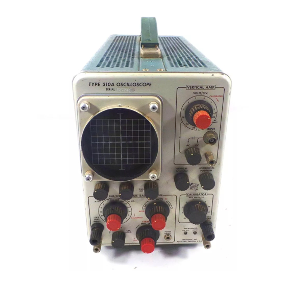
- Page 4 TYPE 310A OSCILLOSCOPE ^VERTICAL AMP]------ v SERIAL VOLTS/DIV HORIZONTAL VERTICAL POSITION POSITION SCALE IL IU M INTENSITY FO C U S , ----- CALIBRATOR E BASE ■TlME/DIV. m i l M il 10 H«« stability RIG. IEVEI M N C A llM A T ID M I t u «XT...
- Page 5 (X) signal to the EXT HORIZ INPUT binding In tro d u c tio n post on the rear panel (Horizontal Display switch set to The Tektronix Type 310A Oscilloscope is a portable EXT HORIZ). The regulated DC power supplies maintain precision instrument designed for equipment maintenance constant output over a wide variation o f line voltages and or calibration at its point o f use.
- Page 6 Specification-Type 310A Characteristic Characteristic Performance Performance Triggering Time Base In te rn a l, e x te rn a l, or line. Trigger Source Sweep Rate Selected by TRIGGER switch. 0.5 microsecond to 0.2 second/ Calibrated range division in 18 steps. Steps in...
-
Page 7: Power Supply
STANDARD ACCESSORIES Type External w ith variable edge light ing. Standard accessories supplied w ith the Type 310A are listed in the Mechanical Parts List at the rear o f this manual. Area Eight divisions vertical by 10 For optional accessories available for use w ith this instru... - Page 8 N O TES...
- Page 9 General voltage. The regulating range fo r each line voltage that this instrument can be wired fo r is as follows. To effectively use the Type 310A, the operation and 99 - 117 volts 110-volts nominal capabilities of the instrument must be known. This section...
- Page 10 Operating Instructions-Type 310A Fifl. 2-2, F ro n t- and rear-panel controls and connectors. 2 -2...
- Page 11 An accessory fan base is available VO LTS/D IV control is not in the fo r use w ith the Type 310A. This fan base is particularly C ALIBR ATED position. useful when the Type 310A is placed in a permanent loca...
- Page 12 Operating Instructions-Type 310A EXT TRIG INPUT Input binding post fo r external trigger Trigger signal. TRIGGER Selects the source and slope of the trigger signal which starts the sweep. Sweep The sweep can be triggered from either TIM E /D IV...
- Page 13 H O R IZ G A IN Clockwise Screwdriver adjustment to set the DC 2. Connect the Type 310A to a power source that meets MAG CENTER level of the horizontal amplifier so de the voltage and frequency requirements of the instrument.
- Page 14 Operating Instructions-Type 310A level of the internal trigger signal, this demonstration shows 12. Turn the Variable VO LTS/D IV control throughout how DC level changes affect DC trigger coupling. Return its range. Notice that the UNCALIBRATED VER TICAL the display to the center of the display area.
- Page 15 Graticule tion w ith this instrument. The graticule o f the Type 310A is scribed on the clear plastic faceplate protector. The graticule is marked w ith G ENERAL OPERATING IN FO R M A TIO N eight vertical and 10 horizontal divisions.
- Page 16 T Y P E 3 1 0 A T E S T S E T U P C H A R T ® Fig. 2-3.
- Page 17 Loading Effect of the Type 310A the probe. Also, to provide the best measurement accuracy, calibrate the vertical gain of the Type 310A at the tempera As nearly as possible, simulate actual operating condi ture at which the measurement is to be made.
- Page 18 This allows amplitude, time rela connected from the Type 310A chassis to the chassis of the tionship or wave shape changes o f signals at various points equipment under test.
- Page 19 Operating ln$truction$-Type 310A trigger signal reaches a DC voltage level selected by the 4. Slowly turn the PRESET ADJUST clockwise until setting o f the TRIG LEVEL control. When using the inter the trace first appears. Note the position of the PRESET nal trigger source, the setting o f the VE R TIC A L POSITION ADJUST.
- Page 20 Operating Instructions-Type 310A Waveforms obtained with the TRIG LEVEL control set in the + region. STABILITY Waveforms obtained with the TRIG LEVEL control set in the — region. Fig. 2-6. E ffect o f the T R IG L E V E L control and triggering slope selection on the C R T display.
- Page 21 Operating Instructions-Type 31OA coupling, see the discussion titled Trigger Coupling in this section. Automatic triggering is obtained in the AUTO position of the Trigger Coupling- Mode switch. In this position, trig gering occurs at the average voltage level of the applied waveform.
- Page 22 Contact your local Tektronix Field Office or repre This control can be adjusted to provide calibrated external sentative fo r assistance in making specific measurements horizontal deflection.
- Page 23 Operating Instructions— Type 310A Position to Centerline Fig. 2-9. Measuring peak-to-peak voltage o f w aveform . 2. Position the trace to the bottom line o f the graticule 5. Turn the VER TICAL POSITION control so the lower or other reference line. If the voltage to be measured is...
- Page 24 Operating Instructions-Type 310A Example. Assume that the vertical distance measured is 3. To establish an arbitrary vertical deflection factor so the amplitude o f an unknown signal can be measured accu 4.6 divisions (see Fig. 2-10), the waveform is above the rately at any setting o f the V O LTS/D IV switch, the ampli...
- Page 25 Operating Instructions-Type 310A in seven horizontal divisions can be determined by using the 2. Set the T IM E /D IV switch and the Variable TIM E / repetition rate formula (step 6): D IV control so one cycle of the signal covers an exact number of horizontal divisions.
- Page 26 Operating Instructions-Type 310A Example. Assume that the distance between the time 5. Set the T IM E /D IV switch to the fastest sweep rate measurement points is five divisions (see Fig. 2-11) and the that displays less than eight divisions between the 10% and T IM E /D IV switch is set to .1 MSEC w ith the magnifier off.
- Page 27 Operating Instructions-Type 310A horizontal 9. M ultiply the distance measured in step 8 by the set TIM E /D IV distance ting of the T IM E /D IV switch. If sweep magnification is (divisions) Settin9 used, divide this answer by 5.
- Page 28 N O TES...
- Page 29 A basic block gain o f the Horizontal A m plifier five times. When the diagram o f the Type 310A is shown in Fig. 3-1. Only the Horizontal Display switch is set to the X5 MAG position,...
- Page 30 CATHODE ®...
- Page 31 V320 is connected to the control grid o f V329. V329 is The effective overall vertical deflection factor o f the Type 310A is determined by the VO LTS/D IV switch, connected as a cathode follower stage and the output at its SW305.
- Page 32 Circuit Description— Type 310A Internal trigger signal to Sweep Trigger circuit Vertical signal from Input Vertical Attenuator Driver Para- deflection (0.1 and above) Cathode phase signal to Followers Amplifier vertical V 430A , V 4 0 1 , Vertical signal...
- Page 33 Circuit Description-Type 310A VO LTS/DIV control is rotated counterclockwise, the resis internal triggering from the signal displayed on the CRT. tance between the cathodes increases to reduce the gain and V465 is connected as a cathode follow er to provide isola...
- Page 34 Circuit Description-Type 310A signals from DC to four megahertz. When the Trigger To start the sweep on the negative slope o f the trigger Coupling-Mode switch is set to the AC or AUTO positions, signal, TRIGGER switch SW2B reverses the connections to the trigger signal must pass through C2.
- Page 35 Circuit Description— Type 310A goes positive to turn V40B off. The output level of this SWEEP G ENERATOR stage returns to the quiescent level near the supply voltage. General Auto Triggering. When the Trigger Coupling-Mode The Sweep Generator circuit produces a sawtooth v o lt...
- Page 36 Circuit Description-Type 310A Unblanking gate to Sawtooth to Horizontal Amplifier Fig. 3-5. Sweep G enerator detailed block diagram. and V150B. The circuit remains in this condition with diodes V150A and V150Band interrupts the current which V102B o ff and V 1 10 on until it is reset by the Reset and was quiescently flowing through them.
- Page 37 Circuit Description-Type 310A trol grid o f V160B goes negative also. This produces a conditions and are ready to produce another sweep as soon positive-going change at the plate o f V160B which is con as the Sweep Gate M ultivibrator stage is ready to receive nected to the grid o f cathode follow er V160A.
- Page 38 Circuit Description-Type 31OA V220B. HORIZONTAL POSITION control R207 sets the External Horizontal Input CF DC level at the grid o f V220B to determine the horizontal In the X I MAG and X5 MAG positions o f the Horizon position o f the display on the CRT. Variable capacitors tal Display switch, the grid o f V220A is connected to C205 and C213 provide adjustment for a linear horizontal ground by SW210C.
- Page 39 Circuit Description— Type 310A V240B and the current through it increases. This increase CALIBRATO R in current through V240B produces a negative-going saw The Calibrator circuit produces a square-wave output tooth at its plate which is connected to the left horizontal voltage.
- Page 40 Circuit Description-Type 310A, the conduction of the -1 5 0 -V o lt Series Regulator stage. binding post. In the fu lly counterclockwise position o f the This output current changes to provide a constant, low- CALIBRATOR switch, the CAL OUT binding post is dis...
- Page 41 Circuit Description-Type 310A S W 6 0 0 POWER Fig. 3-8. L V Power Supply detailed block diagram. 3 -1 3...
- Page 42 Circuit Description-Type 310A CRT C IR C U IT o f +100-Volt Error A m plifier V631 as an error signal. Regulation o f the output voltage is controlled by +100-Volt General Series Regulator V633 in a similar manner to that described The CRT Circuit provides the high voltage and control fo r the —150-Volt Supply.
- Page 43 Circuit Description-Type 310A tubes V720 and V730. The tw o remaining windings provide stage, V701A. V701A amplifies the error signal and pro the control grid and cathode potential fo r the CRT. Both o f duces a control signal to the High-Voltage Oscillator stage.
- Page 44 NO TES...
- Page 45 Exterior. Loose dust accumulation on the outside o f the pull the panel out at the top and lift away from the instru Type 310A can be removed w ith a soft cloth or small paint ment. For best overall operation and safety, leave the brush.
- Page 46 Wiring Color-Code. A ll insulated wire and cable used in recommended. The best check o f tube performance is its the Type 310A is color-coded to facilitate circuit tracing. actual operation in the instrument. More details on check Signal carrying leads are identified w ith one or tw o colored ing tube operation is given under Troubleshooting.
- Page 47 2. Check Associated Equipment. Before proceeding w ith troubleshooting of the Type 310A, check that the NOTE equipment used w ith this instrument is operating correctly. Voltages and waveforms given on the diagrams are Check that the signal is properly connected and that the not absolute and may vary slightly between instru...
- Page 48 1. Use a hot iron fo r a short time. A pply only enough replacements for the Type 310A can be obtained through heat to make the solder flow freely. Use a heat sink to your local Tektronix Field Office or representative. How...
- Page 49 3. Remove the CRT socket. spacers may be re-used if they are not damaged. The applicable Tektronix Part Numbers for the ceramic strips 4. Loosen the CRT clamp at the base o f the CRT shield. and spacers used in this instrument are given in the Mechan...
- Page 50 Replacement tubes should be o f the instrument. If the power transformer becomes defective, original type or a direct replacement. contact your local Tektronix Field Office or representative fo r a warranty replacement (see the Warranty note in the CAUTION fro n t o f this manual).
- Page 51 To assure instrument accuracy, check the calibration of equipment required picture preceding the desired portion. the Type 310A every 500 hours of operation, or every six To prevent unnecessary recalibration o f other parts o f the months if used infrequently. Before complete calibration,...
- Page 52 120 volts amplitude at 50 hertz and one kilohertz repetition rate with a 120 nanosecond or less risetime; 500 17. 10X probe fo r Type 310A. Tektronix P6012 recom m illivolts into 50 ohms at 400 kilohertz w ith a five nano...
-
Page 53: Table Of Contents
Performance Check/Calibration— Type 310A C heck L o w -V o lta g e Power Supply Page 5-8 10. Check/Adjust Vertical Gain (R442) Page 5-12 Regulation REQUIREMENT: Five divisions vertical deflection at .1 VO LTS/D IV w ith 0.5-volt square-wave input. - Page 54 Performance Check/Calibration-Type 310 A position w ith a two-division display at tw o megahertz; P E R F O R M A N C E : C o rre c t _ _ _ , incorrect (list stable display in the AC and DC positions w ith a two- exceptions) _______________________________________ division display at four megahertz.
- Page 55 36. Check Normal Sweep Timing Accuracy Page 5-23 General The follow ing procedure is arranged so the Type 310A REQUIREMENT: Correct tim ing w ithin 0.24 division can be calibrated w ith the least interaction o f adjustments over center eight divisions at each T IM E /D IV switch and reconnection o f equipment.
- Page 56 4. Set the autotransformer o utp ut voltage to the center Preliminary Procedure for Performance Check o f the voltage range fo r which the Type 310A is wired. Only Connect the Type 310A to a power source which 5.
- Page 57 Equipment required for steps 1 through 9 is shown Variable C ALIBR ATE D in Fig. 5-1. Input Coupling b. Separate the chassis o f the Type 310A and swing the Trigger controls right chassis open. TRIGGER +IN T Trigger Coupling-Mode c.
-
Page 58: Adjust High-Voltage Supply And Check
IN TER AC TIO N — May affect operation o f all circuits into correct tolerance. Be sure to recheck the w ithin the Type 310A. -1 5 0 -v o lt and +100 volt supplies fo r correct toler ance after adjustment. Check +100-V olt and +300-V olt Power Supplies 3. -
Page 59: Check Low-Voltage Power Supply Ripple
(If the line voltage is near the center o f Fig. 5 3. Lo cation o f high-voltage test p o in t and ad justm ent (right the regulating range, the Type 310A can be connected side). d irectly to the line; otherwise, leave the instrument con... - Page 60 PERFORMANCE CHECK ONLY fully counterclockwise. Then, slowly rotate it clockwise Rear-panel operational adjustment; can be adjusted as until the trace first appears on the Type 310A CRT. Adjust part of a performance check. the test oscilloscope vertical position control to move the trace to a graticule line near the center horizontal line.
- Page 61 Performance Check/Calibration— Type 310A C H E C K -T he trace should be parallel to the center horizontal line w ithin 0.5 division/10 divisions (i.e., w ith trace positioned to center horizontal line at the farthest left vertical line o f the graticule, the trace must be w ithin 0.5 division o f the center horizontal line at the farthest right vertical line).
-
Page 62: Check/Adjust Vertical Gain (R442)
Performance Check/Calibration-Type 310A T e s t O s c illo s c o p e to -b a n a n a plug u r .w d rlv o r BNC ta b le probe parch card Fig. 5-7. E quipm ent required (o r ilepa 10 through 16. -
Page 63: Check/Adjust Vertical Preamplifier Gain
Performance Check/Calibration— Type 310A cal deflection within 3% in each position of the VO LTS/ D IV switch. TABLE 5-1 Vertical Deflection Accuracy Maximum Standard Vertical VO LTS /D IV error for amplitude deflection switch ±3% accuracy calibrator in divisions... -
Page 64: Check Low-Frequency Linearity
(see Fig. 5-10A). Connect the probe ground strap to with the VERTICAL POSITION control. the Type 310A chassis near the test point, d. Reduce the display to exactly two divisions with the Variable VO LTS /D IV control (keep display centered about f. -
Page 65: C Heck/Adjust Volts/Division Switch
Performance Check/Calibration—Type 310A S q u a r e - w o v e g e n e r a t o r probe 1_ _ GR to BNC B N C -'o -p o tt JX BNC adapte r... - Page 66 Performance Check/Calibration— Type 310A given in Table 5-2 and readjust the generator output ampli tude at each V O LTS /D IV switch setting to maintain a four division display. n. A D JU S T -V O L T S /D IV switch series compensation as given in Table 5-2 for best square corner on the displayed waveform (use low-capacitance screwdriver).
-
Page 67: Check/Adjust Low-Frequency Compen
Performance Check/Calibration-Type 310A waveform (use low capacitance screwdriver). Readjust the generator output amplitude at each setting to maintain a four-division display, or to provide maximum vertical deflection in the 10 position. Fig. 5-12 shows the location of the variable capacitors. -
Page 68: High
Performance Check/Calibration— Type 310A 2 1 . Check/Adjust Preamplifier High-Frequency d. If necessary, adjust the triggering controls for a stable Compensation display. a. Set the V O LTS /D IV switch to .01. e. CHECK—CRT display for square corner and flat top within 0.15 division. -
Page 69: Check Upper Vertical Bandwidth Lim It
Performance Check/Calibration-Type 310A e. CHECK-CRT display 2.8 divisions or greater in 22. Check Upper Vertical Bandwidth Lim it amplitude (not more than - 3 dB). a. Equipment required for steps 22 through 37 is shown in Fig. 5-15. f. Disconnect all test equipment. -
Page 70: Triggering
Performance Check/Calibration-Type 310A LEVEL control may be adjusted as necessary to obtain a 25. Check Low-Frequency Triggering Operation stable display). a. Change the following control settings: VO LTS/DIV q. Set the Trigger Coupling-Mode switch to AUTO. TRIGGER + IN T... -
Page 71: Check/Adjust Sweep Length (R 161)
Performance Check/Calibration— Type 310A VO LT S /D IV b. CHECK—Sweep length between 10.2 and 10.8 divi TRIGGER +IN T sions as shown by 0.2 to 0.8 division of horizontal deflec T IM E /D IV 1 MSEC tion to the right of the tenth vertical line. -
Page 72: Adjust Fligh-Speed Linearity
Performance Check/Calibration-Type 310A 33. Adjust 10-Microsecond Timing CHECK-CRT display for four-division maximum spacing between markers (indicates adequate range for a. Position the first marker to the left vertical line of the continuously variable sweep rate between the calibrated graticule with the HORIZONTAL POSITION control. -
Page 73: Check Normal Sweep Timing Accuracy
Performance Check/Calibration— Type 310A between the second and tenth vertical lines of the graticule. The marker at the tenth vertical line must be within 0.4 division (within 5%) of the line when the marker at the second vertical line is positioned exactly. -
Page 74: Check/Adjust Calibrator Amplitude
C H EC K -C R T display for difference between the Other controls standard amplitude calibrator output level and the Type 310A calibrator output level is 0.3 division (three volts) or VERTICAL Midrange less (calibrator output amplitude, 100 volts ±3%). The... -
Page 75: Check Calibrator Repetition Rate
ADJUST—Cal Adj, R510 (sea Fig. 5-20), for no difference between the standard amplitude calibrator out 40. Check External Horizontal Deflection Factor put level and the Typo 310A calibrator output level, a. Change tho following control settings h. CHECK-Using the CALIBRATOR switch, VOLTS/... -
Page 76: Check External Blanking
(20 volts peak to peak) at one kilohertz. This completes the Calibration Procedure for the Type 310A. Disconnect all test equipment and replace the side d. Remove the ground bar from between the CRT panels. If the instrument has been completely checked and/ CATHODE and GND binding posts on the rear panel. - Page 77 If a part you have ordered has been replaced with a new or improved part, your local Tektronix, Inc. Field Office or representative w ill contact you concerning any change in part number.
- Page 78 PARTS LIST ABBREVIATIONS binding head brass internal length or long binding head steel met. metal cap. capacitor mtg hdw mounting hardware ceramic outside diameter comp composition oval head brass connector conn oval head steel cathode-ray tube part of countersunk pan head brass double end pan head steel diameter...
- Page 79 Type 31OA S E C TIO N 6 ELECTRICAL PARTS LIST Values fixed unless marked Variable. Bulbs Tektronix Part Number B165 Use 150-027 Neon, NE-23 B166 Neon, NE-23 Use 150-027 Use 150-027 B177 10,001-21,331 Neon, NE-23 150-0030-00 B177 21,332-up Neon, NE-2V...
- Page 80 Electrical Parts List— Type 3 1 OA Capacitors (con tin u e d ) Tektronix Part Number C218 .02 /if Cer. 150 v 283-004 C220 12MMf Cer. 500 v 281-506 C240 6.25 300 v - 1 0 % + 100%...
- Page 81 Electrical Parts List— Type 3 1 0 A Capacitors f c o n t i n u e d ) Tektronix Part Number 400 v C639 .01 /if 285-510 C660 40 /if 350 v - 1 0 % + 100% Use 290-0088-00 10,001-10,122 .02/if...
- Page 82 Electrical Parts List— Type 3 1 0 A Resistors Tektronix Part Number Resistors are fixed, composition, ± 1 0 % unless otherwise indicated. 302-105 1 meg 'A w 302-474 470 k 'A w 302-470 47 O 302-822 8.2 k 302-470...
- Page 83 Electrical Parts List— T ype 3 1 0 A Resistors ( c o n tin u e d ) Tektronix Part Number y ,w R150 X21880-up 22 meg 316-0226-00 R160 8.2 k 304-822 R161 Var. Comp. Sweep Length 311-011 R162...
- Page 84 Electrical Parts List— Type 3 1 OA Resistors (con tin u e d ) Tektronix Part Number R325 Prec. 309-099 Vi w R326 301-163 R329 302-183 R340 470 k 302-474 R341 4.7 k 302-472 R342 4.7 k 302-472 R343 470 k...
- Page 85 Electrical P a rt* List— T ype 3 1 OA Resistors (con tin u e d ) Tektronix Part Number Use 323-0401-00 147 k Prec. R462 72 W 302-473 47 k R465 .2 w Var. Hum Balance 311-060 R470 302-270...
- Page 86 Electrical Parts List— Type 3 1 OA Resistors (c o n t in u e d ) Tektronix Part Number R668 20 w 308-031 R669 1 meg 'A w Prec. 309-014 490 k R670 'A w Prec. 309-002 2.2 meg...
- Page 87 Electrical Parts List— Type 31OA Thermal Cut-Out Tektronix Part Number TK600 Thermal Cutout 165°F. 260-227 Transformers T600 Plate and Heater Supply *120-118 T700 CRT Supply 120-121 Electron Tubes 6DJ8 154-187 6DJ8 154-187 V I02 6DJ8 154-187 V I I 0...
- Page 88 S E C TIO N 7 M E C H A N IC A L PARTS LIST Type 310A...
- Page 89 Mechanical Parts List— Type 31OA CABINET S E R I A L / M O D E L N O . REF. D E S C R IP T IO N P A R T N O . N O . EFF.
- Page 90 Mechanical Parts List— Type 310A FRONT T Y P E 3 1 0 A O S C I L L O S C O P E VERTICAL AMP staiAi vom/oiv *4 ' M A I I O IM ' il...
- Page 91 Mechanical Parts List— Type 31OA FRONT (Cont'd) SERIAl/MODEL NO. REF. DESCRIPTION PART NO. EFF. DISC. 366-0029-00 10001 20759 KNOB, large black — TIME/DIV. 366-0142-00 20760 KNOB, large charcoal— TIME/DIV. Includes: SCREW, set, 6-32 x 3 / 1 6 inch HSS 213-0004-00 366-0031-00 KNOB, TIME/DIV., red...
- Page 92 Mechanical Parts List— Type 31OA FRONT IConfd) SERIAL/MODEL NO. REF. PART NO. DESCRIPTION EFF. DISC. 366-0031-00 KNOB, VOLTS/DIV., red Includes: 213-0004-00 SCREW, set, 6-32 x 3 / 1 6 inch HSS 262-0198-00 SWITCH, VOLTS/DIV., wired Includes: 260-0206-00 SWITCH, VOLTS/DIV., unwired 384-0164-00 ROD, extension, aluminum, Ve x 6 7 /i<s inch 406-0339-00...
- Page 93 Mechanical Parts List— Type 310A FRONT (Cont'dj SERIAL/MODEL NO. REF. DESCRIPTION PART NO. EFF. DISC. KNOB, small black— SCALE ILLUM. 366-0033-00 10001 20759 366-0148-00 20760 KNOB, small charcoal— SCALE ILLUM. Includes: 213-0004-00 SCREW, set, 6-32 x inch HSS 3 / u...
- Page 94 Mechanical Parts List— Type 310A RIGHT SIDE (Open) S tR IA l/M O O It NO R tf. PART NO. DESCRIPTION OISC 136-0063-00 10001 18969 SOCKET, 12 pin, CRT 136-0143-00 18970 SOCKET, CRT assembly with 10 leads r/ \ t...
- Page 95 Mechanical Parts List— Type 31OA RIGHT SIDE (Open) (Cont'd) SERIAL/MODEL NO. REF. PART NO. DESCRIPTION EFF. DISC. 10001 124-0090-00 14453 STRIP, ceramic, 3 /4 inch x 9 notches 124-0095-00 14454 STRIP, ceramic, inch x 9 notches T / , 6 Each Includes: 355-0046-00 STUD, nylon...
- Page 96 Mechanical Parts List— Type 3 1 OA RIGHT SIDE (Closed) SER IA L/M O P El NO. DESCRIPTION PART NO. oi sc. PLATE, sub-panel, front 386-0871-00 Mounting Hardware: (not included) SCREW, 6-32 x s /u inch FHS 100* 211 0538-00 LOCKWASHER, steel, internal # 6 210-0006-00 NUT, hex, brass, 6-32 x Vi inch...
- Page 97 Mechanical Parts List— Type 310A RIGHT SIDE (Closed) (Cont’d) SERIAL/MODEL NO. REF. PART NO. DESCRIPTION DISC. 124-0091-00 STRIP, ceramic, 7 / 1 6 inch x 11 notches Each Includes: 355-0046-00 STUD, nylon Mounting Hardware For Each (not included) 361-0008-00 SPACER, nylon,...
- Page 98 Mechanical Parts List— Type 310A POWER CHASSIS 7 - 1 0...
- Page 99 Mechanical Parts List— Type 310A POWER CHASSIS SERIAL/MODEL NO. REF. DESCRIPTION PART NO. EFF. DISC. FRAME, top right, 7 /8 x l 3 ,5/ )8 inches 426-0066-00 Mounting Hardware: (not included) SCREW, 6-32 xVws inch FHS 100° 211-0538-00 CLIP, spring, tube, large...
- Page 100 Mechanical Parts List— Type 310A POWER CHASSIS (Conf’dJ SERIAL/MODEL NO. REF. PART NO. DESCRIPTION EFF. DISC. 211-0511-00 SCREW, 6-32 x inch BHS ' / 2 166-0030-00 TUBE, spacer, aluminum, 7* O D x 3 /^ inch long 210-0006-00 LOCKWASHER, steel, internal...
- Page 101 Mechanical Parts List— Type 3 1 OA LEFT SIDE S IR IA l/M O D C l NO. DESCRIPTION PART N O IFF. DISC. 441 0231 00 CHASSIS, vertical amplifier 260 0096 00 •SWITCH, MAG., rotary Mounting Hardware: (not included w/switch) 210-0413-00 NUT, hex, brass, %-32 x '/2 inch 210 0012 00...
- Page 102 Mechanical Parts List— Type 3 1 0 A VERTICAL AMPLIFIER CHASSIS 7 - 1 4...
- Page 103 Mechanical Parts List— Type 310A VERTICAL AMPLIFIER CHASSIS (Cont'dJ SERIAL/MODEL NO. REF. DESCRIPTION PART NO. EFF. DISC. 426-0067-00 FRAME, top left, 7 / 8 x 147 /i«s inches 344-0014-00 CLIP, spring, tube, large 129-0029-00 POST, connecting 1 inch x 2 notches...
- Page 104 Mechanical Paris List— Type 310A VERTICAL AMPLIFIER CHASSIS (Cont'd) SERIAL/MODEL NO. REF. DESCRIPTION PART NO. EFF. DISC. 124-0089-00 STRIP, ceramic, 3 /4 inch x 7 notches Each Includes: STUD, nylon 355-0046-00 Mounting Hardware For Each: (not included) SPACER, nylon .063 inch high...
- Page 105 Mechanical Parts List— Type 310A VERTICAL AMPLIFIER CHASSIS (Conf'd) SERIAL/MODEL NO. REF. DESCRIPTION PART NO. EFF. DISC. NUT, hex, brass, 4-40 x 3 / 1 (S inch 210-0406-00 LOCKWASHER, steel, internal # 4 210-0004-00 SPACER, aluminum, 3 / Il5 OD x y4 inch long...
- Page 106 Mechanical Parts List— Type 310A REAR 7 - 1 8...
- Page 107 Mechanical Parts List— Type 310A REAR ( C o n t'd l SER IA L/M O DEL N O . REF. DESCRIPTION N O . EFF. DISC. 386-0879-00 10001 12578 PLATE, overlay, power half, blue wrinkle 387-0049-00 12579 13416 PLATE, overlay, power half, blue vinyl...
- Page 108 Mechanical Paris List— Type 31OA REAR (Conf’d) SER IA L/M O DEL N O . REF. DESCRIPTION PART N O . N O . EFF. DISC. 406-0421-00 BRACKET, aluminum, 1 x 3V8 x inches (rear pot) 7 / 14 7 7 / u Mounting Hardware: (not included) 210-0407-00 NUT, hex, brass, 6-32 x 1 /* inch...
- Page 109 Mechanical Parts List— Type 3 1 OA CRT SHIELD S E R IA L /M O D Il NO. DISCRETION PART N O . DISC. CLAMP, CRT, l 7 /)* inches diameter 343-0029-00 Mounting Hardware: (not included) • NUT, keps, 6-32 x 7u inch 210-0457-00 210-0803-00 WASHER, steel, 6L x ’/•...
- Page 110 Mechanical Parts List— Type 31OA STANDARD ACCESSORIES SERIAL/MODEL NO. REF. PART NO. DESCRIPTION EFF. DISC. 378-0509-00 1001 21119 FILTER, light, plexi., green 378-0550-00 21120 24179 FILTER, light, smoke gray 378-0552-00 24180 FILTER, light, blue 10001 24179X 103-0013-00 ADAPTER, 3 to 2 wire 161-0013-00 10001 20219...
- Page 111 S E C T IO N 8 D IA G R A M S The following special symbols are used on the diagrams: Screwdriver adjustment Front- or rear-panel control or connector. Indicates coaxial connector...
- Page 112 SQUARE W AVE CALIBRATOR V50I V52Q T Y P E . 3 I O A O S C I L L O S C O P E...
- Page 113 V 8 5 9 B L O C K D I A G R A M...
- Page 114 D I S P L A Y E D 310A S W P . TPI6. | - - - - - - - - - - - - - - - - - - - - - - - - - - - - - - - - - - - - - 1 TRIGCitR L O U P L IN C , H O O t. |...
- Page 115 V 4 0 TRIGGER MULTIVIBRATOR $ 9 2 2 M A Y 3 E S U B S T I T U T E D T O R $ D J 6 . SE E PARTS LIST FOR EARLIER VALUES AND SERIAL NUMBER RANGES OF PARTS MARKED WITH BLUE OUTUNE.
- Page 117 M IL L E R RUNUP CIRCUIT '■300V DISCONNECT DIODES 2 500 5000 .SLC V / 5 0 B j 6 A L 5 i > RII5 • 3S0 _ _ C / / 5 ■/SO SEE SWEEP TIMING SWITCH DETAIL S E E PAR TS LIST FO R EAR LIER VALUES AND SERIAL NUMBER 6 9 2 2 OR 6BQ7A M A Y B E SU B STITUTED...
- Page 118 T il I----------------1 " ' r ‘ 5W/75C SW/75A SW/75B TO CATH, PIN J , VI60A SWEEP-GEN. C.F. (SWEEP) sw > TYPE. 3 /0 A OSCILLOSCOPE...
- Page 119 \T IM E /D IV .\ — 1------------------------- -----------------------------------1 SW/75C SW I75D...
- Page 120 C O N DITIO NS SC O PE u n d e r t e s t VOLTAGE R E A D IN G S U P P E R R E A D I N G S - H O R I Z O N T A L P O S IT IO N C O N T R O L C C W L O W E R R E A D IN G S - H O R IZ O N T A L P O S IT IO N C O N T R O L S W E E P S T A B I L I T Y C O N T R O L C C W...
- Page 121 V240A V2403 O U T P U T A M P L IF IE R V220A V2205 IN P U T C Fs +300V +300 H WITH BLUE OUTUNE. H O R IZ O N T A L A M P L / F / L R 0,4.9 C IR C U IT NUMBERS 2 .
- Page 122 I---------------1------------------------- 1------------1 ------------------------------------------- 1 ---------------- 1 ------------------------------------------------------- - \ V 0LTS 3 W 3 0 S A 3 W 3 0 S B 3 W 3 0 5 C 3 W 3 0 5 D 3W 303C. 3 W 3 0 5 F T Y P E -3 /0 A O S C IL L O S C O P E...
- Page 123 - \ V 0 L T 5 / D I V . \ - I----------- I-------------------T ----------1 5 W 3 0 5 C , 5 W 3 0 5 H 5 W 3 0 3 J 3 W 3 0 3 K . N O T L .- FO R AO O lTtO NA L D E C O U P LIN G NC TWOR.KS S E E...
- Page 124 V40/ V430t V40a V430L IN PU T D R IV E R C A M P L IF IE R S D E C O U P LIN G N E T W O R K S -------- T Y P E 3 / 0 A OSCILLOSCOPE...
- Page 125 V 465 V 4 4 0 TRIGGCR P/CKOff V430A V 4 3 0 B V 4 4 1 DRIVER CFs O U TP U T A M P L IF IE R S +IOOV N O T E : o r SCOPE UNDER T E S T FOR H U M B A L A N C E C O N TR O L READINGS SEE HEATER W IRING D IA G R A M...
- Page 126 4 , 5 V 6 6 V 6 3 / V 6 0 2 V 5 2 0 * u> 9 F R O M 6 3 H 6 6 3 H 6 6 3 H 6 a A U G T L R M .
- Page 127 C O N D I T I O N S ) D C O P E . ( J N D = R T E . ’b T V O i_T A < S £ R E A D I N C 5 7663 A L L V O L T A C E 'S , T A K E N...
- Page 128 V704 U N B L A N K IN G OSCILLATOR F R O M CATH, M 7 B (S t T 700 + 9ov B + IOOV I V70/A SHUNT REGULATOR V70/3 17720 C OM PARATOR 5642 + 4 0 0 V + 3 0 0 7 UNREG TO 'X' 7 7 2 0...
- Page 129 C R T CIRCUIT ® C IR C U IT NUMBfcRS 7 0 0 T H R U 7 6 0...
- Page 130 CALIBRATOR MULTIVIBRATOR CAL. A D J. © SE E PARTS LIST F i C O N D I T I O N S S C O P E . U N D E - R T E S T VALUES AND S E R RANGES OF PART ( t o o v ) C A L I B R A T O R ..............
- Page 131 C A L IB R A T O R CATHODE. F O L L O W E R +IOOV CALIBRATOR c .* * C IR C U IT NUM Bfep.S SOO T H R U 5 4 9...
- Page 132 M A N U A L C H A N G E IN F O R M A T IO N At Tektronix, we continually strive to keep up with latest electronic developments by adding circuit and component improvements to our instruments as soon as they are devel...
Need help?
Do you have a question about the 310A and is the answer not in the manual?
Questions and answers