Table of Contents
Advertisement
Pulse input
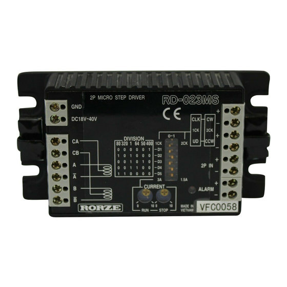
2-PH Selectable Microstepping Motor Driver
Lower vibration
R
D
-
0
2
3
M
S
R
D
-
0
2
3
M
S
R
D
-
0
2
3
M
S
C o m p a c t
80,000 steps/rev. (max.)
Features
Compliant with CE Marking
Lower vibration
Selectable microstep (22 selections)
Photo-isolated inputs and outputs
Selectable clock – 1clk. or 2clk. Input
Auto. current down (Adjustable stop current)
Suitable Motors
Manufacturer
Model No.
RORZE Co.
RM24 , RM26
HB type (PM type)
OTHER
2-ph stepping motor
(6 lead wires)
Motor Wiring
Wiring Diagram
6 LEAD WIRE MOTOR
26
Specifications
Supply voltage
18 to 40VDC (including ripple)
Approx. 1.2 times rated coil current
Supply current
of motor (max.)
Motor current
0.3 to 3A/phase
Unipolar, constant current
Drive method
chopper method
Up to 400 microsteps/step
Selections:1,2,4,8,16,32,64,
Microstep resolution
2.5,5,10,20,40,80,160,320,
6.25,12.5,25,50,100,200,400
0 to 80% of the run current after
Auto. current down
about 0.3 seconds of inactivity
according to Stop Current setting
Response frequency
500kpps max.
Overheating, over current
,
Protective circuitry
& low voltage protection
Outside dimensions
27.5(H) 105(W) 56(D)mm
Weight
approx. 250g
Functions
Clock inputs (CW/CLK, CCW/UD)
In case of using Two Clock Input (2CK)
CW+/-
Motor rotates one step in CW direction with a pulse
current from CW+ to CW- terminal.
CCW+/- Motor rotates one step in CCW direction with a pulse
current from CCW+ to CCW- terminal.
In case of using One Clock Input (1CK)
CLK+/- & UD+/-
Motor rotates one step in CW direction with a pulse
current from CLK+ to CLK- terminal and UD input off.
Motor rotates one step in CCW direction with a pulse
current from CLK+ to CLK- terminal and UD input
turned ON.
Full Step Input (2P IN +/-)
Motor rotates in full step mode with a pulse current from "2P IN +"
to "2P IN –".
Alarm Output (ALARM +/-)
When the internal temperature of the driver reaches about 70 ,
ALARM output is turned ON and ALARM LED will light.
Also, a motor will stop and auto. current down will work.
If the body temperature drops about 10
below the triggered
temperature, returns automatically.
ALARM LED
This will light when Overheating protection circuit is in operation.
Run Current Adjustment Trimmer
Trimmer to adjust the drive current.
Stop Current Adjustment Trimmer
Trimmer to set the stop current to any value between 0 to 80% of
the run current.
Dip Switches
1) Select Clock Input (1CK/2CK)
2) Select Microstep Resolution (D1-D5)
3) Select Current Range (3A/1.5A)
Dimensions
Torque Chart
Supply Voltage
24VDC
Motor Current
3A/Phase
Driver RD-023MS
Excitation Mode Microstep (Resolution 50)
Motor RM2640D
Damper
D6CL-6.3F
Supply Voltage
24VDC
Motor Current
3A/Phase
Driver RD-023MS
Excitation Mode Microstep (Resolution 50)
Motor RM2690D
Damper
D6CL-6.3F
Supply Voltage
24VDC
Motor Current
3A/Phase
Driver RD-023MS
Excitation Mode Microstep (Resolution 50)
Motor RM26A3D
Damper
D6CL-6.3F
(mm)
27
Advertisement
Table of Contents

Related Manuals for Rorze RD-023MS

Summary of Contents for Rorze RD-023MS
- Page 1 2-PH Selectable Microstepping Motor Driver Supply Voltage 24VDC Lower vibration Clock inputs (CW/CLK, CCW/UD) Motor Current 3A/Phase Driver RD-023MS Excitation Mode Microstep (Resolution 50) Motor RM2640D Damper D6CL-6.3F In case of using Two Clock Input (2CK) C o m p a c t...
- Page 2 Instruction Manual Selectable Microstep 2-ph Stepping Motor Driver RD-023MS RORZE CORPORATION...
- Page 4 If you will use this product in devices like the above, please contact us. It should be noted that RORZE will not be responsible for any damage caused by using a product in such a device without the consent of RORZE. !...
-
Page 5: Table Of Contents
Table of Contents 1.Description....................1 2.Features ....................1 3.Specifications ................... 2 4.Part Name ....................2 5.Current Adjustment .................. 3 5-1 Run Current Adjustment Trimmer..........3 5-2 Stop Current Adjustment Trimmer ..........3 6.Terminals ....................4 6-1 Clock Input and Direction Input (CW/CLK, CCW/UD) ....4 6-2 Full Step Input (2P IN +/-) ............ -
Page 6: 1.Description
The RD-023MS is a high resolution stepping motor driver featuring selectable microstep. Microstep drive is the drive method to resolve a basic step angle of motor by controlling the current applying to the motor. -
Page 7: 3.Specifications
500 kpps max. (at 4.5V to 5.5V) Weight Approx. 250g (8.8oz.) Outside dimensions 27.5H x 105W x 56Dmm (1.1”H x 4.1”W x 2.2”D) 4.Part Name RD-023MS 2P MICRO STEP DRIVER G N D + POWER SUPPLY C L K DC18V-40V -... -
Page 8: 5.Current Adjustment
You can set the stop current to any value between 0 and 80% of the run current by adjusting Stop Current Adjustment Trimmer. (Setting at shipment is 50 %.) Stop Current Adjustment Trimmer Graduations Fig.4. Stop Current Setting RD-023MS... -
Page 9: 6.Terminals
6. Terminals 6.Terminals 6-1 Clock Input and Direction Input (CW/CLK, CCW/UD) ! Caution Please set the current between clock input terminals in the range of 8 to 20mA. Do not exceed 20mA because of the danger of failure. Do not set the current to 8mA or less because of the danger of malfunction. Two Clock Input (2CK) (Inputs two clock pulses - CW clock pulse and CCW clock pulse) CW+/-... -
Page 10: Full Step Input (2P In +/-)
Motor rotates in full step mode with a pulse current of 2 to 10mA (approx. 3.8mA at 5V) from “2P IN +” to “2P IN –”. 6-3 Alarm Output (ALARM +/-) Overheating protection circuit intervenes turning ALARM output ON. (Open collector output ON) 7.ALARM LED This will light when Overheating protection circuit is in operation. RD-023MS... -
Page 11: 8.Dip Switches
8. Dip Switches 8.Dip Switches 1.5A Fig.6. Dip switches 8-1 Clock Input Selection Switch (1CK/2CK) Selects clock input, Two clock input method (2CK) or Pulse & Direction input method (1CK). 8-2 Microstep Resolution Selection Switch (D1 to D5) ! Caution Do not set the dip switches except the below table. -
Page 12: 9.Timing Diagrams
Note2: The pulse count will not be lost as long as parameters T1 to T3 are within the spec. Note3: Motor will rotate 1 step at the rising edge of pulse (CW・CCW・CLK). (When the clock current will change from ON to OFF) RD-023MS... -
Page 13: 10.Input/Output Circuits
10. Input/Output Circuits 10.Input/Output Circuits ! Caution Do not exceed max. rated current・voltage of each I/O circuit. It causes failure or malfunction. 10-1 Clock Input Circuits (CW/CLK, CCW/UD) 270Ω + CLK/CW Inside 1kΩ UD/CCW - Photo-coupler 8-20mA Fig.10. Clock Inputs Please operate with a pulse current of 8 to 20mA. -
Page 14: 11.Wiring Diagram
You can use any HB(hybrid) or PM(permanent magnet) stepping motor with rating of 0.3 to 3A/ph. Select motors with rating of less than supply voltage × 0.7(V). RORZE 2-Ph Stepping Motors (Torque -- 1kgf・cm = 13.9oz・in Inertia -- 1g・c㎡ = 5.46745×10 oz・in... -
Page 15: 12.Heat Dissipation
12. Heat Dissipation 13. Other Functions 14. Consumption Current 12.Heat Dissipation ! Caution Please dissipate heat generated by driver and motor enough. If it is insufficient, temperature rise causes malfunction, failure or fire. Keep the motor’s maximum case temperature below 100℃ and driver’s below 60℃ by adjusting the drive current or by installing a cooling fin, fan, etc. -
Page 16: 15.Relationship Between Frequency(Pps) And Motor Speed(Rpm)
1.8/10×10,000×60 Motor speed(rpm)=──────────= 300 rpm 16.Dimensions 1 05 m m (4 . 13 " ) 9 5 mm ( 3. 7 4 ") 2P MICRO STEP DRIVER RD-023MS G N D + C L K DC18V-40V - D I V I S IO N +... - Page 17 40V DC, they do not correspond to Machinery Directive and Low Voltage Directive. The entire system including RD-023MS and all the control device and electric parts, is subject to EMC Directive. Therefore, please make sure of the final EMC conformity of your system or machinery into...
- Page 19 1588 Michinoue, Kannabe-cho, Fukayasu-gun, Hiroshima 720-2104, Japan Phone: +81-84-960-0001 +81-84-960-0200 Fax: E-mail address: sales@rorze.com Home page address: http://www.rorze.com *All RORZE products come with a 24-month guarantee. *Specifications and products are subject to change without any obligation on the part of the manufacturer. RCD 020201...
Need help?
Do you have a question about the RD-023MS and is the answer not in the manual?
Questions and answers