Table of Contents
Advertisement
Quick Links
Advertisement
Table of Contents

Subscribe to Our Youtube Channel
Related Manuals for FlaktWoods FICO FCLA-128

Summary of Contents for FlaktWoods FICO FCLA-128
- Page 1 Cotrol system FICO-128 Installation, use and maintenance 09/2014...
-
Page 2: Table Of Contents
Contents Connection instructions, system with individual indication ..................3 Topology of FICO FCLA-128 with one and two communication loops ..............4 Topology of FICO FCLA-128 with two communication loops and four fan interlocks (Groups A, B, C, and D) ..............................5 Control unit FCLA-128 .............................. -
Page 3: Connection Instructions, System With Individual Indication
INSTALLATION, USE AND MAINTENANCE Control System FICO-128 1 Connection instructions, system with individual indication 1 Connection instructions, system with nect the included 2.2 kohm resistor to the smoke detector between connectors 1 and 5. individual indication If you use Calectro EVC-PY-DA smoke detectors, you must 1.1 General connect the 2.2 kohm resistor to the smoke detector between connectors 1 and 3. -
Page 4: Topology Of Fico Fcla-128 With One And Two Communication Loops
INSTALLATION, USE AND MAINTENANCE Control System FICO-128 2 Topology of FICO FCLA-128 with one and two communication loops FCLA-128 FICO Output fire alarm Supply 230 V Output service alarm Communication to parent system Interlocking of fan FAN 1 FCBA-2 Supply 230V... -
Page 5: Topology Of Fico Fcla-128 With Two Communication Loops And Four Fan Interlocks (Groups A, B, C, And D)
INSTALLATION, USE AND MAINTENANCE Control System FICO-128 3 Topology of FICO FCLA-128 with two communication loops and four fan interlocks (Groups A, B, C, and D) FCLA-128 FICO Output fire alarm Supply 230 V Output service alarm Communication to parent system... -
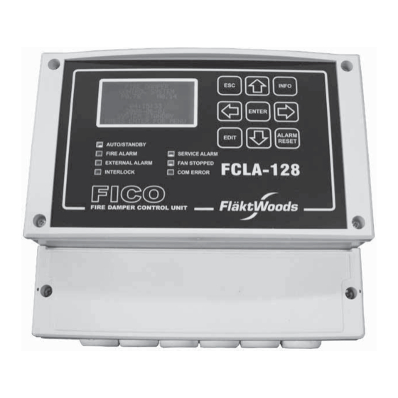
Page 6: Control Unit Fcla-128
INSTALLATION, USE AND MAINTENANCE Control System FICO-128 4 Control unit FCLA-128 INFO ENTER ALARM EDIT AUTO/STANBY DAMPER TEST RESET FIRE ALARM SERVICE ALARM FCLA-128 EXTERNAL ALARM FAN STOPPED INTERLOCK COM ERROR FICO FIRE DAMPER CONTROL UNIT LINK1 LINK 2 MODBUS SYSTEM MODBUS Max 32 UNITS/LINK... -
Page 7: Communication Unit Fcba-2 And Relay Unit Fcfa-1
INSTALLATION, USE AND MAINTENANCE Control System FICO-128 5 Communication unit FCBA-2 and relay unit FCFA-1 Communication unit FCBA-2 COMM. KOMM. 230 VAC STATUS PROG. COMM ERR LINK MOTOR- MOTOR- MOTOR DETECTOR SWITCHES MOTOR SWITCHES DETECTOR ADDRESS 0-99 UPDATE DAMPER TEST Supply connection AC 230 V DIP switch activating damper motor and smoke detector Indicators for damper position and status of smoke detector... - Page 8 INSTALLATION, USE AND MAINTENANCE Control System FICO-128 Relay unit FCFA-1 POWER ON FAN ON COMM ERR LINK ADDRESS UPDATE ADR GRP 230 VAC LINK Supply connection AC 230 V Connection for fan interlocking Connection for communication loop (input and output) LEDs indicating operating status Address switch Updating of relay unit...
-
Page 9: Installing Communication Unit Fcba-2
INSTALLATION, USE AND MAINTENANCE Control System FICO-128 6 Installing communication unit FCBA-2 Note! All installation work must be done with power to On numbering of FCBA-2, the system disconnected. see Figure (page 7) Connect power supply cables AC 230 V to communication unit 230 VAC FCBA-2 according to high-voltage regulations. -
Page 10: Installing Control Unit Fcla-128
INSTALLATION, USE AND MAINTENANCE Control System FICO-128 7 Installing control unit FCLA-128 Note! All installation work must be done with power to On numbering of FCLA-128, the system disconnected. see Figure (page 6) Connect power supply cables AC 230 V to control unit FCLA- 230 VAC 128 according to high-voltage regulations. -
Page 11: Taking Fcla-128 With Its Fcba-2 Communication Units Into Use
INSTALLATION, USE AND MAINTENANCE Control System FICO-128 During any configuration, the system shall be in Standby. See Chapter 9.2 8 Taking FCLA-128 with its FCBA-2 communication units into use Example of taking into use a system with three communication units, all of which are to be connected to fan interlock- Chapter 9;... - Page 12 INSTALLATION, USE AND MAINTENANCE Control System FICO-128 Log into the system using code 1000. Use the arrow keys to select a number, and press PASSWORD ENTER after each number. If your code was correct Login level 1 is shown. Press ENTER. ENTER Setting language, date, and time: Go to Settings using the arrow keys, and press ENTER.
- Page 13 INSTALLATION, USE AND MAINTENANCE Control System FICO-128 Under the System menu you must activate the communication units (En). Press EDIT twice. Press ARROW UP to activate communication unit with ad- dress 01, then press ENTER. Group A is always preselected (to change fan group, see chapter 10).
- Page 14 INSTALLATION, USE AND MAINTENANCE Control System FICO-128 Go to Test & Maintenance to set the time and interval for damper test. Go to Schedule and press ENTER to enter the next menu. Select Test time (= desired time for damper test). Press EDIT, set hours and minutes using the arrow keys, press ENTER to finish.
- Page 15 INSTALLATION, USE AND MAINTENANCE Control System FICO-128 9 Settings 9.1 Logging into the system Press ENTER on the control unit to enter Menu. Go to Log in using the arrow keys, and press ENTER. Log into the system using code 1000. Use the arrow keys to select a number and press PASSWORD ENTER after each number.
-
Page 16: Adding / Changing Fan Groups
INSTALLATION, USE AND MAINTENANCE Control System FICO-128 10 Adding / changing fan groups The system must be in Standby before you can do the opera- tions below. If the system is not in Standby, see Chapter 9.2. Go to the Config system menu, select System, and press ENTER. -
Page 17: Manual Test Of Dampers, Communication Units, And Groups
INSTALLATION, USE AND MAINTENANCE Control System FICO-128 12 Manual test of dampers, communication units, and groups Log into the system using code 1000, see Chapter 9.1. Press ENTER to enter Menu. Select Test & maintenance using the arrow keys, then press ENTER. - Page 18 INSTALLATION, USE AND MAINTENANCE Control System FICO-128 13 Shutting off a communication unit to allow main- tenance of damper without activating alarm Log into the system using code 1000. Select Test & maintenance using the arrow keys, then press ENTER. Go to Service mode and press ENTER.
-
Page 19: Adding A Communication Unit To The System
INSTALLATION, USE AND MAINTENANCE Control System FICO-128 14 Adding a communication unit to the system Connect all peripheral devices to communication unit accord- ing to installation instructions; see Chapter 5. Connect communication loop to communication unit. Commu- FCLA-128 FCBA-2 FCBA-2 nication units shall be connected in series. - Page 20 INSTALLATION, USE AND MAINTENANCE Control System FICO-128 Press ENTER. The whole system is now in Standby, press ESC. Go to Config system and press ENTER. Go to System and press ENTER. Select line with address, for example 04, and activate it using the arrow keys.
-
Page 21: Adding A Relay Unit To The System
INSTALLATION, USE AND MAINTENANCE Control System FICO-128 15 Adding a relay unit to the system Connect all peripheral devices to relay unit according to con- nection instructions; see Chapter 5. FCLA-128 FCBA-2 FCFA-1 Connect communication loop to relay unit. Relay units shall be connected in series with each other and the existing units in the communication loop. - Page 22 INSTALLATION, USE AND MAINTENANCE Control System FICO-128 Press ENTER. The whole system is now in Standby, press ESC. Go to Config system and press ENTER. Go to System and press ENTER. Select the line for the communication unit that shall be con- nected to the new fan Group (C).
-
Page 23: Connecting Damper Motor / Smoke Detector To A Communication Unit With Only One Damper Motor / Smoke Detector Connected To It
INSTALLATION, USE AND MAINTENANCE Control System FICO-128 16 Connecting damper motor / smoke detector to a communication unit with only one damper motor / smoke detector connected to it Start by shutting down the communication unit to which a damper motor / smoke detector is to be added. Go to Log in on the control unit using the arrow keys, and press ENTER. -
Page 24: Disconnecting Damper Motor / Smoke Detector From A Communication Unit With Two Damper Motors / Smoke Detectors Connected To It
INSTALLATION, USE AND MAINTENANCE Control System FICO-128 17 Disconnecting damper motor / smoke detector from a communication unit with two damper motors / smoke detectors connected to it Start by shutting down the communication unit from which a damper motor / smoke detector is to be disconnected. Go to Log in on the control unit using the arrow keys, and press ENTER. -
Page 25: Disconnecting Communication Unit / Relay Unit From The System
INSTALLATION, USE AND MAINTENANCE Control System FICO-128 18 Disconnecting communication unit / relay unit from the system Go to Log in on the control unit using the arrow keys, and press ENTER. Log into the system using code 1000. Go to System mode and press ENTER. Select Mode and press EDIT, then press ARROW DOWN and then ENTER. -
Page 26: Alarms At Control Unit Fcla-128
INSTALLATION, USE AND MAINTENANCE Control System FICO-128 19 Alarms at control unit FCLA-128 AUTO/STANDBY illuminates green when power is connected. AUTO/STANBY DAMPER TEST AUTO/STANDBY flashes green when the system is in STAND- FIRE ALARM SERVICE ALARM BY, and power is connected. FAN STOPPED EXTERNAL ALARM AUTO/STANDBY flashes green when the system is in STAND-... -
Page 27: Alarms At Communication Unit Fcba-2
INSTALLATION, USE AND MAINTENANCE Control System FICO-128 20 Alarms at communication unit FCBA-2 LED illuminates green when damper is open. LED flashes green when damper is open but its opening has taken more than 3 minutes (damper movement sluggish). Flashing green and yellow LED indicates that damper is stuck between end positions. -
Page 28: Alarm Codes And Situations In Fcla-128 Shown In Alarm History
INSTALLATION, USE AND MAINTENANCE Control System FICO-128 21 Alarm codes and situations in FCLA-128 shown in Alarm History USER: Log in USER: Log out USER: Wrong password System start Power failure Fire Alarm Service Alarm Damper failure External Alarm Interlock Comm Error Damper test 22 Systems with battery in equipment where... - Page 29 INSTALLATION, USE AND MAINTENANCE Control System FICO-128 23 Resetting control unit FCLA-128 to factory settings Go to Log in using the arrow keys, and then press ENTER. Log into the system using code 2000. Use the arrow keys to select a number and press PASSWORD ENTER after each number.
-
Page 30: Aid For System Documentation
INSTALLATION, USE AND MAINTENANCE Control System FICO-128 24 Aid for system documentation Installation: Date: Drawing identifier of control unit FCLA-128: Damper test interval: Time: or Day of the week: Interlocking group: (A-J) Drawing identifiers of equipment/fans included in interlocking group: Communication unit FCBA-2 Drawing identifiers Left... - Page 31 INSTALLATION, USE AND MAINTENANCE Control System FICO-128 Communication unit FCBA-2 N o: Left Right Damper Smoke detector Damper Smoke detector Fläkt Woods FIFLO EN 2014.09 All rights reserved.
- Page 32 Fläkt Woods Oy Kalevantie 39 FI-20520 Turku, FINLAND Tel. +358 20 442 3000 www.flaktwoods.com...
Need help?
Do you have a question about the FICO FCLA-128 and is the answer not in the manual?
Questions and answers