
Summary of Contents for Auto Pro-Up DBL-STAR STD/MINI
- Page 1 DBL-STAR STD/MINI Brake Drums & Rotors Lathe OPERATING MANUAL Auto Pro-Up Company. Revision: 02/17 Seongok-dong 732-1, Danwon, Ansan, Gyeonggi 15616 South Korea 82-34-4349009...
-
Page 2: Table Of Contents
Table of Contents 1. Premise 2. Safety Cautions 3. Receiving & Unpacking 4. Installation 5. Machine Description 6. Operating Panel Descriptions 7. Tool Bits 8. Chip Deflector 9. Arbor and Adapters Care 10. Mounting Rotors 11. Mounting Drums 12. Install Twin cutter 13. -
Page 3: Premise
1. PREMISE DBL-STAR STD has been designed and built to ensure long lasting, high-level operating reliability. This operating manual is part of the machine. Keep this manual near the machine for immediate reference. Read carefully before use. ◆ The user is responsible for the proper use of the machine in accordance with the instructions found in this operating manual. -
Page 4: Safety Cautions
2. Safety Cautions This machine is intended for use by QUALIFIED PERSONNEL only. Make certain all operators are properly trained, know how to safely and correctly operate the unit. 1) Pre-Use Safety Educating yourself about the lathe before using it can prevent many accidents. Read the user manual before you start work. -
Page 5: Receiving & Unpacking
3. Receiving & Unpacking The shipment is packed by standard export carton box. If any of the goods are shorted or damaged, notify manufacturer at once. -
Page 6: Installation
In the shipment, there should be two separate carton boxes which contains standard accessories with accessory check sheet. They are labeled as Pack 1 & Pack 2. Pack 1 contains dry items while Pack 2 contains oil-treated items. All accessories on the Pack 2 are oil or grease coated to protect machined surfaces from rust during ocean transit. -
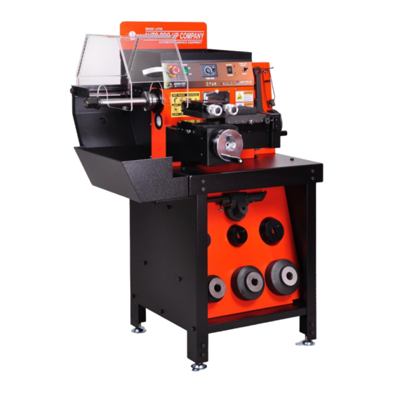
Page 7: Machine Description
5. Machine Description Tool Tray Safety Guard w/LED lights Accessory Rack 1.25”Arbor & Arbor Nut Operating Panel Twin cutter X-Axis Feed Handwheel Limit Switch Removable Chip Collector Dust Boot Y-Axis Feed Handwheel Accessory Rack Horizontal Adjustment Feet Control Box Fuse Power Cord Ventilated Motor Assembly Cover... - Page 8 Machine Dimensions...
-
Page 9: Operating Panel Descriptions
6. Operating Panel Description Power On/OFF Rotor/Drum Feed Rate Switch Selection Switch Knob Emergency Stop Feed Rotor/Drum Switch On/OFF Indicators The Lathe requires a single-phase power source of 110V, 60 Hz, fused at 10A for proper operation. Should an extension cord be required use the one rated to handle this electrical specifications only. Do not modify a cord or plug. -
Page 10: Tool Bits
7. Tool Bits Step.1 Step.2 Step.1 Use provided 4.0mm Allen wrench to unbolt tool bit holders. Then replace worn tool bits with new bits by using flat-head screwdriver. NEVER operate the lathe with a worn or broken tool bits. It can not only cause poor cut but also tool bit holders to contact the rotor or drum surface. -
Page 11: Arbor And Adapters Care
9. Arbor and Adapters Care Arbor and accessories are most important components when machining. Even the smallest scratch or loose metal chip can cause incorrect and unstable rotor or drum alignment. This will eventually lead to bad cut. Arbor shaft and accessories need to be checked and maintained by operator with great care. -
Page 12: Mounting Rotors
10.Mounting Rotors Clean the rotor mounting surfaces before mounting the rotor. Use a wire brush or sandpaper to clean all mounting surfaces of burrs and rust. The inside diameter of the center hole must be thoroughly cleaned as well to ensure accurate mounting. Typical Hubless Rotors Mounting. - Page 13 Typical Hubbed Rotors Hubbed rotors are mounted with two centering cones to center the rotor and spacers for setup. After mounting the rotor, it may be necessary to use spacers to fill out the arbor so the arbor nut can be tightened down securely. The spacer must always be used next to the arbor nut.
-
Page 14: Mounting Drums
11. Mounting Drums Hubbed drums are mounted with centering cones or double taper cones (sold separately) that contact the drum near the middle of the bearing races. Hubless drums are held in place on the arbor by the hole cup and centered by centering cones. Machined surface of the hole cup must contact the bolt hole surface of the drum. - Page 15 Use below illustrations as a guide when choosing right adapters for rotors and drums. Little Ideal size small small of Cup Pay particular attention when choosing adapters. Using proper adapters in width and length (cups, centering cones and spacers) is crucial to achieve optimum cutting experience.
-
Page 16: Install Twin Cutter
12. Install Twin Cutter Tool Slots Tool Slides Clean the tool slides and bottom of the twin cutter. Install the twin cutter onto tool slides over the bolt and secure with 14mm hex nut. Adjust position of the bolt from two tool slots as illustrated below. -
Page 17: Install Drum Boring Bar And Clamp
13. Install Drum Boring Bar & Clamp Drum boring clamp has same tool slide key on the bottom as twin cutter Mount boring clamp to the most appropriate tool slide location depends on the drum diameter If a twin cutter is installed, remove it and install the boring bar. Hold twin cutter and remove hex nut by using provided wrench. -
Page 18: Feed Device
14. Feed Device The Push-pull switch sets the feed to move in and out automatically or manually. Turn the handwheel clockwise to move the crossfeed inward towards the rotor or the drum. Turn in counterclockwise to move the crossfeed away from the rotor or drum. For Drum, tool slide will move left and right by handwheel-moving the tool bit into and out of drum. -
Page 19: Rotor Micro Dial
15. Rotor Micro Dial Move the crossfeed in towards the lathe and center the twin cutter so the rotor is between the tool bits. As long as hex nut is not fully tightened, the twin cutter has enough room to move and align with the rotor properly without moving the feed. -
Page 20: Drum Micro Dial
16. Drum Micro Dial The dial has an inch scale as well as metric scale. Drum depth-of-cut dial is used to select the amount of material to be cut from the inside drum diameter. Etched Mark Depth of cut lock Drum Depth Knob collar... - Page 21 - Grease crossfeed and rotor & drum lead screws monthly. - Grease the dovetail ways monthly. Always brush metal chips and debris from the operating areas of the lathe. Leadscrews Maintenance Lubricate leadscrew and keep the dovetail way lightly oiled monthly. Center Block Leadscrew Dovetail...
-
Page 22: Electronic Components
18. Electronic Components Feed Motor and Limit Switch Feed Motor Regularly inspect the limit switch. Check for any exposed or damaged wires. When the limit switch is pushed, clear “clicking” sound must be heard. - Page 23 1HP Geared Motor...
- Page 24 Operating Panel Parts Part No. Part Description EGS-017 Emergency Stop Switch EGS-018 Main Power Switch EGS-019 Rotor/Drum Selector EGS-021 LED work light Selector EGS-022 Electronic Feed Controller...
- Page 25 LED Safety Guard...
- Page 26 Twin Cutter Assembly...
Need help?
Do you have a question about the DBL-STAR STD/MINI and is the answer not in the manual?
Questions and answers