Advertisement
Features
Charges Lithium Polymer, Lithium Ion and A123 packs. Charges any brand of pack. Accepts
Cellpro Adapters for plug-and-play compatibility.
Accepts Cellpro node connectors, which enable the charger to monitor each cell during charg-
ing and independently charge each cell to its optimum level. Charger includes two adapters
for charging 2s to 4s Cellpro packs having 5-pin node connectors.
Charges one 1s to 10s pack, or two 1s to 5s packs simultaneously. When two packs are con-
nected to the charger, internal electronic switches connect the packs in series.
Up to 10A charge current (318W continuous input and 260W continuous output at 15.7V input).
Up to 3.0C charge rate, the fastest in the industry.
Charges packs through node connectors with or without connecting main discharge wires to
charger. Compensates for discharge wire lengths up to six feet with 1mV accuracy.
Displays individual cell internal resistance to 0.1milliohm, an exclusive feature for estimating
pack quality and finding bad cells.
Backlit LCD display provides easy readability.
Bidirectional PC interface enables extensive charger setup using free Charge Control Soft-
ware. Configure custom presets, adjust speaker volume, set LCD contrast and control many
other settings.
Charge Optimization can be set for an accurate 1mV cell balance or for Faster Charging (with
less balance) using the Charge Control Software.
Charge Control Software automatically checks for software and charger firmware updates.
Update charger firmware without sending the charger back to the factory.
Works with a wide range of power supplies, even those not rated for high power. Easily
changes from moderate current bench supply at home to car battery at the field.
Intelligent controller performs extensive checks to prevent damage to packs and power supply.
Precautions
Follow all instructions in this manual to assure safe operation.
IMPORTANT: Do not disconnect or connect packs while the charger is charging.
Always watch LiPo packs while they are charging. Never leave LiPo packs unsupervised dur-
ing charging.
See additional warning sheets provided with FMA LiPo packs.
Follow all guidelines for charging, discharging, handling and storing LiPo cells.
Minor arcing may occur when discharge wires are connected to the charger before charging.
This is normal.
FMA, Inc.
5713 Industry Lane, Suite 50
Sales: (800) 343-2934
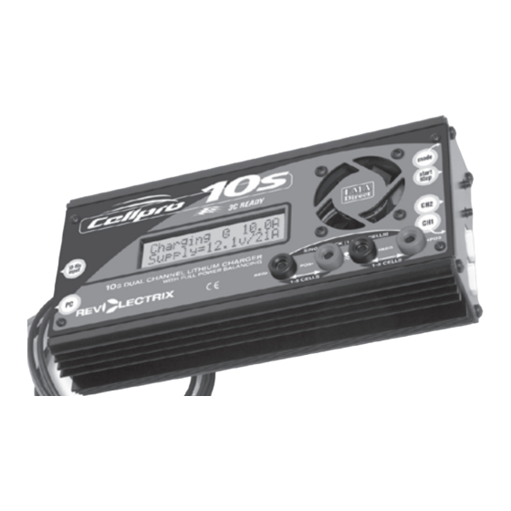
Cellpro 10s Charger
Model LC10S10ADC, for use with LiPo, Li-Ion and A123
battery packs with node connectors
10 Amp model for automatic and manual charging with
cell balancing and overcharge protection
Technical: (301) 668-4280
Frederick, MD 21704
www.fmadirect.com
Advertisement
Table of Contents

Related Manuals for FMA Direct Revolectrix Cellpro 10s


Summary of Contents for FMA Direct Revolectrix Cellpro 10s
- Page 1 Cellpro 10s Charger Model LC10S10ADC, for use with LiPo, Li-Ion and A123 battery packs with node connectors 10 Amp model for automatic and manual charging with cell balancing and overcharge protection Features Charges Lithium Polymer, Lithium Ion and A123 packs. Charges any brand of pack. Accepts Cellpro Adapters for plug-and-play compatibility. Accepts Cellpro node connectors, which enable the charger to monitor each cell during charg- ing and independently charge each cell to its optimum level. Charger includes two adapters for charging 2s to 4s Cellpro packs having 5-pin node connectors. Charges one 1s to 10s pack, or two 1s to 5s packs simultaneously. When two packs are con- ...
- Page 2 Parts Cellpro 10s Charger 2 6-pin to 5-pin node connector adapters (to enable Cellpro packs equipped with 5-pin con- nectors to be charged using the Cellpro 10s Charger) Plug Blocker (to enable charging packs without connecting discharge wires) Optional: FUIM2 PC connectivity set (required for using the Charge Control Software) Charger and pack terminology Auto mini- fuse Mode button To power Start/Stop button source Channel 2 node connector Channel 1 node connector Connect FUIM2 here when Display Channel 1 Channel 2 using Charge Control Software Banana jacks for discharge wires when charging two...
- Page 3 Understanding the Cellpro 10s Charger You can set the Cellpro 10s Charger’s charge rate to one of three Auto modes—1C, 2C or 3C—as appropriate for the pack(s) being charged. When one of these rates is selected, the charger determines the pack’s capacity and automatically sets the correct output current using FMA’s ad- vanced Fuel Gauging technology. You can also manually set charge current to any value between 0.1A and 10A in 0.1A increments. Finally, you can select Storage Charge mode which charges to 50% rated capacity using Fuel Gauging technology. The charger handles multiple chemistries and charge parameter presets. When one pack is connected to the charger, the pack is intially charged at the selected charge rate (or the maximum charge rate possible). Using Ohm’s law, the maximum charge rate (Amps) is derived from the maximum power (Watts) the charger can produce without overheating. Maximum power is approximately 300W measured at the charger input (FMA rates maximum power using a 15V DC input source). Maximum power depends on many factors including pack imbalance during charge, input (supply) voltage, output (charge) voltage, DC/DC converter ef- ficiency (which varies between 80% and 90% depending on the relationship of supply voltage-to- charge voltage), ambient temperature, and internal operating temperature. Peak Power = Maximum input power charger draws for first 3-5 minutes of charge. When the pack reaches about 90% capacity, the charger enters balance charge mode.
- Page 4 utes at 3C. However, if the packs have different capacities, or were discharged to different levels, charging for the pair could take longer than expected. Since the charger supports fast balance cur- rent of 1A, all other things being equal, the charger still outperforms competing brands. In most in- stances, by the time the first pack is fully charged, the second pack is already approaching constant voltage charge mode; the battery pack itself is the limiting factor in charge time, not the charger. Example 1: You are powering an aircraft with two 4s 2100mAh packs connected in series. Because those packs have the same capacity, and were discharged to about the same level, you can expect them to charge in about the same time. It would be appropriate to charge them simultaneously using the Cellpro 10s Charger. Example 2: You are powering one aircraft with a 3s 500mAh pack, and other air- craft with a 5s 5000mAh pack. If you charge these packs simultaneously using the Cellpro 10s Charger, it would probably take a long time (the 500mAh pack would become full first, then the charger would switch to its 1A balancing rate to fill up 5000mAh pack, which could take several hours). In this case, it would be faster to charge these packs separately because the charger can then apply optimum (and substantially different) charge currents to each pack.
-
Page 5: Connecting Packs To The Charger
Connecting packs to the charger General information If a pack has both a node connector and discharge wires, you can charge using the node con- nector only, or both node connector and discharge wires. When charging two packs simul- taneously, both packs must be connected the same way: either node connectors only, or both node connectors and discharge wires. When charging only through a node connector, the charger balances individual cells. However, charge current is limited to 4A to protect the small node connector wires. When charging through both node connector and discharge wires, the charger balances individual cells and measures individual cell internal resistances. Charge current is not limited to 4A. When charging only one pack, always plug that pack into the charger’s Ch1 jack. When charging only one pack using its discharge wires and node connector, always connect the discharge wires to the charger’s outermost banana jacks. When charging one or two packs without using discharge wires, you must plug the Plug ... - Page 6 Connecting one 1s to 10s Cellpro pack 1. How you connect the Cellpro pack’s node connector(s) to the charger depends on the pack’s configuration. Find the pack’s configuration in the diagrams below, then connect as shown in that diagram. 6-pin to 5-pin 1s to 4s Adapter Cellpro pack Cellpro pack Pack positive and higher-numbered nodes 6s to 9s Cellpro pack 6-pin to 5-pin...
- Page 7 Connecting two 1s to 5s Cellpro packs 1. How you connect the Cellpro packs’ node connectors to the charger depends on the packs’ configurations. Find the configurations in the diagrams below, then connect as shown in that diagram. 6-pin to 5-pin 1s to 4s Adapter Cellpro pack 6-pin to 5-pin 1s to 4s Adapter Cellpro pack 6-pin to 5-pin 1s to 4s...
-
Page 8: Applying Power To The Charger
Applying power to the charger To apply power to the charger: Connect the charger to a 12V to 15V bench power supply, field battery or car battery. If your bench power supply is equipped with banana jacks for output, you can remove the plier clamps from the charger’s input cables and plug the cables directly into the power supply jacks. When the charger is powered up, it displays the following screens in sequence: FMA Cellpro 10s Welcome screen [firmware version]* 2 Packs Charge Last-used preset... - Page 9 Operating the charger You operate the charger using the Mode button and Start/Stop button on the right side of the charger: Mode button: enables you to select a preset, change preset values and display charging data during charging. Start/Stop button: enables you to start charging after you have selected a preset, and to stop charging at any time. Using these buttons you can: Select a preset (see “Selecting a preset”). Change charge settings for any preset (see “Changing a preset”). Charge the attached pack(s) and view real-time operating information (see “Charging a pack or packs”). Selecting a preset To determine the currently selected preset and review its settings: Press the Mode button on the charger’s right side. To select a different preset: Press the Mode button until you see the desired preset’s name and settings in the display, then wait until you see the Safe to Connect screen.
- Page 10 b. Press and release the Mode button until you see the chemistry you want. Choices are: Lithium Poly 4.20V Lithium Ion 4.20V Lithium Ion 4.10V A123 3.65V To change the charge current: a. Press and hold the Mode button, then release it when the display changes to this: Choose Chg. Amps Hold for More Exit Note: If you hold the Mode button down longer, you’ll see (described below) Choose Chemistry (described above).
- Page 11 Charging a pack or packs 1. Before charging, pack(s) must be properly connected to the charger. See “Connecting packs to the charger,” earlier in this manual, for details. 2. Press the Start/Stop button for one second to enter Charging Mode. 3. You will see the following screens in sequence: Checking Pack(s) CHARGING Press MODE for info. 4. While in Charge Mode, you can take the following actions: To view pack and operating data: Press the Mode button repeatedly to cycle through the following screens. (These examples assume two packs are being charged; if one pack is being charged, only the top line may appear in some screens.) C 0.5A 00:00:59 Charge current and charge time. Supply=13.8V/ 1A Supply voltage and input current.
- Page 12 If the charger detects a problem, it will stop charging and display a safety code. If this happens: 1. Press the Mode button to reset the charger. 2. Reconnect the battery properly. 3. Press the Start/Stop button to continue charging. To stop charging: Press the Start/Stop button for one second. The charger displays the ...
-
Page 13: Using The Charge Control Software
5. Under Choose a default Web browser, click Internet Explorer. 6. Click OK. 7. Close the Add or Remove Programs dialog and the Control Panel dialog. After installing the Charge Control Software, you can revert back to your preferred browser. Launching the Charge Control Software Start > All Programs > FMA Direct > Cellpro 10s 2. If your computer is connected to the Internet at this time, the program will check to see whether a new version is available. If a new version is available, you will have the option to install the new version or launch the version you already have. 3. After the program launches, and if your computer is connected to the Internet, the program will check to see whether a new version of the charger firmware is available. If new firmware is available, a message will appear; click OK to close the message window. See “Updating... - Page 14 Monitoring charging operations To monitor cell voltages, total pack voltage and related charging parameters during charg- ing: Click the Cells tab. To monitor cell internal resistances during charging: Click the Int. Res. tab. Note: For the charger to calculate internal resistances, a) pack discharge wires must be connected during charging and b) pack must be at less than 80% fuel level.
- Page 15 Defining presets You can define up to six preset charging configurations. Each preset consists of a name, a chem- istry and a charge current. See “Selecting a preset,” earlier in this manual, for instructions on selecting a preset for charging. Note: Remember that presets can be overridden at the charger. Preset changes made at the charger are retained in the charger until manually changed again, or until a new group of presets is downloaded to the charger.
- Page 16 Recording charge data The Charge Control Software can record charge data for each charging session. 1. Press the Start/Stop button on the charger to start a session. 2. When prompted, enter a file name. You can enter a file name you previously used, but you must confirm that you want to overwrite older data. Charge data is stored in a semicolon-delimited format, which can be imported into a spreadsheet for analysis. Updating charger firmware The Charge Control Software automatically checks for new firmware each time it is launched (as- suming the computer is connected to the Internet).
-
Page 17: Estimating Performance Factors
Estimating performance factors If you don’t have a way to directly measure your propulsion system’s electrical parameters, the Cellpro 10s Charger enables you to estimate them using before- and after-flight measurements. Collect data Charge pack. When charging is finished, record Fuel % and total pack voltage (i.e. sum of cell voltages). Fly plane (or test on the ground). Record flight time in minutes. Connect pack to charger. Record Fuel % and total pack voltage. Calculate performance factors (Fuel % before flight) –... -
Page 18: Troubleshooting
Troubleshooting There are 26 ways to improperly connect two packs to a charger! After the Start/Stop button is pressed, a special battery checking sequence automatically checks every wire before closing the internal switches (if discharge wires are not used during charging). It is possible to get an unre- lated safety code from a simple wiring issue. Operating errors appear as messages in the display. To determine the problem, look up the de- scription below. Correct the error. If errors continue, contact FMA Customer Service. Message Problem 2 Pack Con. Err Check pack wiring Amps too low Reset the charger Bad EEPROM Write Internal error Bad FET supply voltage Check the input voltage Bad Mode Number Internal error Bypass Overvolt Check the pack wiring C2 Pack Detected... -
Page 19: Specifications
Pack wiring issues can cause nuisance safety codes. If any of the safety codes below appear, try connecting the pack to the banana jacks and node connectors without using the plug blocker. Safety code Problem 60-65 Positive switch close failure 66-71 Series switch close failure 72-77 Negative switch close failure Greater than 42V detected 79-80 Cell count out of range (internal software check) 81-86 Charge switch close failure Voltage steady timeout... - Page 20 Quick start for the Cellpro 10s Charger Refer to manual for complete operating details. A. Connect charger to a 12V to 16V (maximum) power source. B. Connect pack(s) to charger. Plug pack’s node connector(s) into channel jack(s) on right side of the charger (use node connector adapters as needed). When charging only one pack, plug pack’s node connector into Ch1. Plug pack’s dis- charge wires into outermost banana jacks on charger’s panel. When charging two packs: Plug discharge wires from Ch1 pack into banana jack pair #1, ...
Need help?
Do you have a question about the Revolectrix Cellpro 10s and is the answer not in the manual?
Questions and answers
cellpro 10s how to wire a 6s battery to charger
To wire a 6S battery to the FMA Direct Cellpro 10s charger:
1. Connect Power Source: Plug the charger into a 12V to 16V DC power supply.
2. Connect Balance (Node) Connector:
- Plug the 6S battery’s balance (node) connector into Channel 1 (Ch1) jack on the right side of the charger.
- Use a node connector adapter if needed for compatibility.
3. Connect Discharge Wires:
- Plug the battery’s main discharge wires into the outermost banana jacks on the charger’s front panel.
4. Optional:
- If not using discharge wires for charging, insert the Plug Blocker into the outermost banana jacks.
5. Configure Charger:
- Press the Mode button to view or select the correct preset.
- To change chemistry or charge current, press and hold the Mode button, then adjust settings.
Make sure the preset matches the battery type and desired charge current.
This answer is automatically generated
Have a Revolution CellPro 10S purchased in 2009. It works fine, but is there any reason to update the firmware? If recommended, please give me instructions and let me know what type of cable plugs in to the PC slot on the charger.
It is not strictly necessary to update the firmware for the FMA Direct Cellpro 10s, but if a new version is available, the program will notify you and give the option to update. To connect the charger to a PC, you need the FUIM2 interface, which includes a 3-pin connector for the charger and a USB connector for the computer.
This answer is automatically generated