
Related Manuals for Automatic Heating Modulex EXT 440


Summary of Contents for Automatic Heating Modulex EXT 440
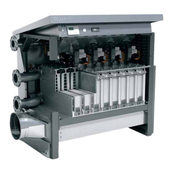
- Page 1 Modulex EXT 440 - 550 - 660 - 770 - 900 Modular Condensing Boiler Installation and Servicing Instructions...
-
Page 2: Table Of Contents
Warning: this manual contains instructions to be used exclusively by the installer and/or a competent person in accordance with the current laws in force. The end user MUST not make any alterations to the boiler. Failure to follow the instructions indicated in this manual, which is supplied with the boiler, could cause injury to persons, animals or damage to property. -
Page 3: General Information
General information GENERAL INFORMATION 1.1 - SYMBOLS USED IN THIS GUIDE When reading this guide particular care has to be given to the parts marked with the followings symbols: DANGER! WARNING! NOTE! Indicates serious danger Indicates a potentially dangerous Suggestions for the for your personal safety situation for the product and the user... -
Page 4: Safety Warnings
General information 1.4 - SAFETY WARNINGS WARNING! The device should not be used by people with reduced physical, mental and sensory, experience and knowledge. These people must be well-informed and supervised during the work. Children must be supervised so they do not play with the appliance. WARNING! The installation, adjustment, and servicing of this appliance must be carried out by a competent person and installed in accordance with the current standards and regulations. -
Page 5: Data Badge
General information 1.5 - DATA PLATE - The essential requirements of the Directive regarding 2004/108 EC electromagnetic compatibility (Directive CE Marking - The essential requirements of the Efficiency Directive The CE marking documents that the boilers satisfy: (Directive 92/42/EEC) - The essential requirements of the Directive regarding gas - The essential requirements of the low voltage Directive 2009-142 EC appliances (Directive... -
Page 6: General Warnings
General information 1.6 - GENERAL WARNINGS This instruction manual is an integral and indispensable part In the event of failure and/or faulty functioning of the appliance, of the product and must be retained by the person in charge switch off the boiler. Do not attempt to make any repairs: contact qualified technicians. -
Page 7: Technical Features And Dimensions
Technical features and dimensions TECHNICAL FEATURES AND DIMENSIONS 2.1 - TECHNICAL FEATURES • Logic of operation: A) Output sharing on as many modules as possible at min. • MODULEX is a compact, gas fired, Low NO , condensing load (down to 22 kW) for the max. efficiency.. boiler, made up by one sectional boiler body, B) Automatic operation hour splitting-up system for each This boiler body consists of two or more modules (from 4 to... -
Page 8: Dimensions
Technical features and dimensions 2.2 - DIMENSIONS FRONT VIEW RIGHT HAND SIDE VIEW 62,5 LEFT HAND SIDE VIEW UPPER VIEW Smoke outlet: Left side (standard condition) Right side Back side MODULEX Dimension No. of Modules 1448 Height 1448 1448 1448 1448 1623 Width... -
Page 9: Performance Data
Technical features and dimensions 2.3 - PERFORMANCE DATA BOILER TYPE MODULEX Appliance category 2H3P Nominal Heat Input on P.C.I. Qn Minimum Heat Input on P.C.I. Qmin Nominal Output (Tr 60 / Tm 80 °C) Pn 424,35 530,44 636,53 742,62 849,05 Minimum Output (Tr 60 / Tm 80 °C) Pn min 20,57 20,57... -
Page 10: Rhs View Showing Main Components
Technical features and dimensions 2.4 - R.H. SIDE VIEW, WITH MAIN COMPONENTS GAS PIPE CONTROLL PANEL GAS VALVE BURNER COVER AUTOMATIC IGNITION AIR VENT ELECTRODE C.H. H. LIMIT FLOW THERMOSTAT BURNER ALUMINIUM/ SILICON HEAT EXCHANGER C.H. RETURN CONDENSATE COLLECTING TRAY- SMOKE MANIFOLD BOILER... -
Page 11: Instructions For The Installer
Instructions for the installer INSTRUCTIONS FOR THE INSTALLER 3.1 - GENERAL WARNINGS WARNING! WARNING! This boiler has to be destined for the use for In rooms where there is the presence of which it has been expressively designed for. aggressive vapours or dust the appliance Any other use shall be considered improper must operate independently from the air and therefore dangerous. -
Page 12: Installation Standards
Instructions for the installer 3.2 - STANDARD CODES FOR INSTALLATION The appliance must be installed in compliance to the Moreover, the boiler must be installed in accordance to all the instructions contained in this manual. regulations regarding the boiler room, the building regulations and the prescriptions regarding central heating plants in force The installation must be carried out by a competent qualified in the country where the boiler is installed. -
Page 13: Packaging
Instructions for the installer - PACKING The boiler MODULEX is delivered assembled and protected by a plastic bag inside a strong cardboard box and fixed on pallet. This allows the boiler to be handled also by forklift. The boi- ler, with the packaging, can go through a door of 800 mm, whereas, without packaging, it can go through a door of 700 mm. - Page 14 Instructions for the installer BOILER UNLOADING AND PACKAGE REMOVAL WARNING! WARNING! Waypoints bands for lifting. Brackets must be Handling with forklift or hoist bands, mounted on bearing stringers. T ma x 5 0°C/ 1 22 °F T mi n - 5 °C /2 3°F M ax.
- Page 15 Instructions for the installer 3.4 - BOILER LOCATION INSIDE A BOILER HOUSE Special attention shall be paid to local regulations and laws about boiler houses and particularly to the obligation of keeping minimum clearances and empty space around the boiler. The installation shall be in compliance with all latest regulations and laws about boiler houses, installations of heating and hot-water systems, ventilation, chimneys capable of evacuating the flue gases of condensing boilers and any...
-
Page 16: Boiler Location In A Boiler Room
Instructions for the installer 3.5 - INSTALLATION When the appliance is installed on existing systems, ensure - The system has been cleaned of impurities and lime scale. yourself that: When a Modulex boiler is installed onto an existing heating system: - The flue outlet pipe is suitable for condensing boilers, for In case the replacement of an existing boiler in an old system the temperature of the products of combustion, calculated... -
Page 17: Gas Connection
Instructions for the installer 3.7 - GAS CONNECTION The gas supply pipe must be connected to the boiler via the Before installing the boiler it is recommended to thoroughly clean all the supply piping in order R 3” respective pipe connection as indicated on page 9. -
Page 18: Connection Return And Flow System Pipes
Instructions for the installer 3.8 - FLOW AND RETURN PIPE CONNEC- TIONS The CH flow and return circuits have to be connected to the WARNING! 4” boiler via the respective connections M and R as indicated IT IS ABSOLUTELY FORBIDDEN TO FIT ON-OFF on page 9. -
Page 19: Primary Circuit Pump Or Boiler Pump
Instructions for the installer 3.9 - DETERMINATION OF PRIMARY BOILER PUMP OR BOILER SYSTEM PUMP The size of the pumps must be determined The boiler pump must have a delivery head which can ensure by installers or technical engineers the water flow rate as shown in the diagram “Water pressure according to boiler data and system design. -
Page 20: Additional Safety And Control Devices According To The Italian Law
Instructions for the installer 3.10 - ADDITIONAL SAFETY AND CONTROL DEVICES ACCORDING TO THE ITALIAN LAW pressure existing in the generator. It must be graduated in “bar” and must have the maximum operating pressure in CERTIFICATION OF THE ADDITIONAL SAFETY DEVICES: scale and be equipped with a 3-way valve with the connection for the manometer. -
Page 21: Wiring Diagram For Additional Safety Devices
Instructions for the installer PRIMARY OR BOILER CIRCUIT KIT, WITH ADDITIONAL SAFETY 3.11 - WIRING DIAGRAM FOR ADDITIONAL DEVICES SAFETY DEVICES MODULEX 440 - 550 - 660 - 700: (COMPO S. 00361994) (PREMO S. 00362065) (PREMO C. 00362067) ON-OFF PUMP MODULEX 900 Pump management via E8 (COMPO S. -
Page 22: Safety Pressure Relief Valve
Instructions for the installer 3.12- PRESSURE RELIEF VALVE DRAIN Note: PIPE Modulex 660 - 770 - 900 need 2 security valve. A pressure relief valve must be fitted on the flow pipe, within 0,5 m from the boiler. It must be dimensioned for the capacity of the boiler and must comply to the regulations in force, SAFETY VALVE... -
Page 23: Boiler Freeze Protection
Instructions for the installer materials present in the system, and mainly with the .15 - BOILER FREEZE PROTECTION aluminum. Should the flow temperature (measured at global flow tempera- ture NTC) decrease under 7°C, the system pump is set up. Shoul WARNING temperature decrease to under 3°C, all modules will start at min. -
Page 24: Condensing Drain
Instructions for the installer 3.17 - CONDENSATE DRAIN Is forbidden discharge the condensate through the rain Discharge of condensate must be: gutters, given the risk of ice and degradation of the - Built in order to prevent the escape of gas products of the materials normally used. -
Page 25: Water Treatment
Instructions for the installer 3.18 - WATER TREATMENT The chemical-physical characteristics of the filling water and Vice versa, if the pH value is between 6,5 and 8, the aluminium reinstatement water in heating systems are of fundamental surfaces of the boiler body are passivated and protected from importance for guaranteeing correct and safe boiler operation. -
Page 26: Flue Chimney Connection
Instructions for the installer 3.19 - CONNECTION TO THE CHIMNEY In a condensing boiler the smokes are evacuated at a very As PVDF (polyvinildimethylfluorure) or PPS (polypropylene low temperature (Max about 84°C). Then it is necessary that transparent simple) certified for this use. Other materials ant the chimney is perfectly impermeble to the condensate of the thicknesses are also autorized provided they can guarantee, combustion products and is made of materials corrosion resi-... - Page 27 Instructions for the installer Chimney dimension Flue Gas Temperature 40°C DIN 4705 Pressure avaible 40 Pa CO levels kg/h kg/s 2520 0,700 1037 1400 1400 2160 0,600 1200 1200 d400 1800 0,500 1000 1000 1440 0,400 1260 0,350 1080 0,300 d315 0,250 0,200...
-
Page 28: Operation
Instructions for the installer 3.20 - BOILER OPERATION The MODULEX EXT is made of inter-linked modules; each In case of more heat request by heating or DHW systems, the module is made of: boiler starts up and water will be heated by the aluminium - Combustion Chamber boiler body - Burner... - Page 29 Instructions for the installer When there is a heat request from the E8 controller or from a 4 thermal elements of 50 kW each working BCM (Boiler Cascade Manager), the E8 or BCM calculates at 50% of the output give = 100 kW = (200%), the necessary output according to the difference between the i.e.
-
Page 30: Electrical Connections
Instructions for the installer 3.22 - ELECTRICAL CONNECTIONS Mains electrical supply connection 230V The electric connections of the boiler are shown in the section Regulations in force named “WIRING DIAGRAMS” A mains supply of 230 V – 50 Hz is required. The wiring to the The gas and water feeding pipes and the CH system pipes boiler must be in accordance with the current CEI regulations. -
Page 31: Functional Wiring Diagram
Instructions for the installer 3.23 - FUNCTIONAL WIRING DIAGRAM eBUS Note: The pictures shown on the Set point remote Ext sens (Cascade actual wiring diagram, is purely open 82°C manager) Ω CONTROL 100 K °C indicative. MODULATION PLC / Ω PUMP °C EMERGENCY... - Page 32 Instructions for the installer 1° MODULE END MODULE VM (A) VM (A) VM (A) ST 2 ST 2 ST 2 FILTER FILTER BLACK BLACK BROWN YEL-GREEN LIGHT BLUE BLUE BLUE BROWN BLUE 3° - 8° MODULES YEL-GREEN BLUE(N) BROWN (L1) BLACK (-) BLUE (TACHO) BROWN (PWM)
-
Page 33: Wiring Diagram For Connection And Managing
Instructions for the installer 3.24 - WIRING DIAGRAM FOR CONNECTIONS AND MANAGING On the back side of the E8 regulator there are two terminal The main controls, necessary for the C.H. system manage- blocks, of which one is for the mains (230 V) connections and ment and for the boiler control, as well some components the other one is for the low tension connections. - Page 34 Instructions for the installer Sensor terminal assignments Terminal VII Connection to BCM Pin 1: eBUS (FA) or 0-10V output Pin 2: (Ground) Terminal I Buffer storage tank low sensor Buf. stor. tank middle sensor / FBR heat. circ. 1 (room sensor) Buf.
-
Page 35: Installation Examples (Functional Wiring And Connections Description)
Instructions for the installer 3.25 - INSTALLATION EXAMPLES (functional wiring and connections description) INSTALLATION OF A BOILER WITH CONNECTION TO A DIRECT HEATING ZONE Heating Circuit 1 (1) Flow sensor heating circuit 1 (9-10) outdoor sensor (10) Ground outdoor sensor (4) Pump heating circuit 1 This sensor can also remain unused (4) Collector pump... - Page 36 Instructions for the installer INSTALLATION OF A BOILER WITH CONNECTION TO ONE MIXED AND ONE DIRECT HEATING ZONES + D.H.W. PROD. This sensor can also remain unused (4-5) Flow sensor heating circuit 2 (1) Flow sensor heating circuit 1 (10) Ground outdoor sensor (6-7) Storage tank sensor F Ric.
- Page 37 Instructions for the installer INSTALLATION OF A BOILER WITH CONNECTION TO TWO MIXED ZONES + D.H.W. PRODUCTION BY SOLAR PANELS necessary for mixing valve control (4-5) Flow sensor heating circuit 2 (1) Flow sensor heating circuit 1 (10) Ground outdoor sensor (6-7) Storage tank sensor (9-10) outdoor sensor (4) Pump heating circuit 1...
- Page 38 Instructions for the installer INSTALLATION OF A BOILER WITH CONNECTION TO TWO MIXED ZONES + D.H.W. PRODUCTION F Ric. Heating Circuit 1 Heating Circuit 2 Remote Boiler Sensor Master Outside Sensor Safety devices kit Slave 1 Filtro Primary system pump Slave 2 Safety devices kit Mixing Header...
-
Page 39: Cascade Manager Bcm
Instructions for the installer 3.26 - CASCADE MANAGER (BCM) Application: Special functions The BCM completes the range of functions offered by the Emergency: it avoids system shutdown caused by an Modulex boilers: interruption in communication with the boiler plant’s - ON/OFF alarm control automation system: - Control of a modulating header pump with the aim of - Input for “Constant setpoint”... - Page 40 Instructions for the installer Connection for boilers in a cascade arrangement managed by a external E8 SLAVE 1 MASTER CanBUS 1 for each cascade of boiler - Cascade Manager Switch ‘’C’’ (see pag. 47) in Position II SLAVE 2 BCM in series Forniture Position In this configuration, switch ‚‘‘C‘‘...
- Page 41 Instructions for the installer Connection for boilers in a cascade arrangement connected to an external BCM optional and managed by PLC/BMS (E8 disconnected). PLC/BMS board BCM board SLAVE 1 eBUS Modbus Modbus (Pos 0) - System Manager - Cascade Manager - System Monitor - System Supervisor (Pos 1÷7)
-
Page 42: Connections For Boilers In Cascade, Controlled By Outer Compensators
Instructions for the installer Connection for boilers in a cascade arrangement managed by an external PLC (E8 disconnected) Board PLC/BMS SLAVE 1 Modbus 1 for each cascade of boiler (Pos 0) - System Supervisor - Cascade Manager (Pos 1÷7) Switch ‘’C’’ (see pag. 47) in Position 0 (for each boilers) SLAVE 2... -
Page 43: Configuration With A Modulating Pump
Instructions for the installer 3.27 - CONFIGURATION WITH A: MODULATING PUMP MODULATING PUMP he BCM board elaborates the data concerning the thermal TERMINALS 0-10 V Mains supply INTERFACE 230 V -50 Hz head (Ät between primary flow and return and supplied WILO MODULATING PUMP heat output). -
Page 44: Filling The System
Instructions for the installer 3.28 - FILLING THE SYSTEM Warning! Never use such a tap to drain the system, since the system dirt Do not mix the CH system’s water with anti- could gather in the boiler and compromise its operation. The freeze or anti-corrosion solutions using wrong system itself shall be equipped with its own draining tap, whose concentrations! It could cause damage to the... -
Page 45: Burner Adjustment
Instructions for the installer 3.29 - BURNER ADJUSTMENT WARNING! All the instructions indicated below are for the exclusive use of qualified UNICAL service technicians or installers. All the boilers are supplied already calibrated and tested. If it is necessary to change the calibration due to gas conversion or adaptation to the mains supply system, the gas valve must be re-calibrated. - Page 46 Instructions for the installer COMPLETION OF THE BASIC Follow this procedure also for the other bur- ADJUSTMENTS ners If the CO percentage is too low, check if the air and smoke Check the C0 values at the minimum and maximum outlet ducts are not obstructed.
- Page 47 Instructions for the installer SWEEPER MODE Before open the operating flap turn clock-wise Shaft encoder, to symbol pen the operating flap, Turn Turn displayed anticlok-wise anticlok-wise After 2 sec SERVICE DATA/TIME GENERAL DISPLAY is displayed level Press to open the level RELAY TEST Turn clok-wise...
-
Page 48: Emergency Functions
Instructions for the installer 3.30 - EMERGENCY FUNCTIONS The BCM It avoids system shutdown in case the main Change-over Series/Parallel boiler plant’s system E8 5064 management is out of Emergency is active or the control is use. managed by PLC or BMS Series connection (the cascade is managed by the BCM, YELLOW LED = Blinking... -
Page 49: Initial Lightning
Instructions for the installer 3.31 INITIAL LIGHTING PRELIMIARY CHECKS The first ignition must be carried out by a there are no water leaks; qualified technician. Failure to do so could cause injury to persons, animals or damage all the necessary ventilation conditions and minimum cle- to property. -
Page 50: Servicing Schedule
Servicing schedule SERVICING SCHEDULE To ensure the continued safe and efficient INSTRUCTIONS FOR SERVICING operation of the boiler it is highly recommended that it is checked at regular To ensure a long life to all your boiler intervals and serviced when necessary, and components and in order not to alter the that only original spare parts are used. - Page 51 Servicing schedule We recommend that periodical service is made by qualified technical personnel according to the frequency stated by national rules in force. As much as the dust present in the air will be sucked inside the combustion chamber, the smoke side resistance will increase, which, finally, will result in a reduced heat input (and consequently a reduced output).
- Page 52 Servicing schedule - Remove the red silicone pipe and then the fans room • Screws on thermal elements Remove the screws “A”, fixing the burner covers, - Sganciare la molla di fissaggio camera ventilatori (with a 13 mm socket or open wrengh) (lato destro/sinistro).
- Page 53 Servicing schedule - move up the burners block (Front) - move up the rear burner block and remove the 2 pins with 5 mm hex key to reach the holes ‘’C’’ (left and right). - Remove the screws gas collector (left and right side). - Remove the four screws with a 36 mm socket wrengh, then the gas flange - Remove gas fittings from the gas manifold with flat key...
- Page 54 Servicing schedule phase – Cleaning • Remove from their seat the sealing gaskets and the bur- ners. • Make a dry-cleaning by blowing compressed air on the “ flame” side of the burner • Visually check the condition of the welds of the metal spon- ge burner.
-
Page 55: Ce Certificate
DISTRIBUTED BY 51 Assembly Tullamarine Vic 3043 Australia PO Box 356 Tullamarine Vic 3043 Australia Telephone +61 3 9330 3300 Facsimile +61 3 9310 5655 Email sales@automaticheating.com.au www.automaticheating.com.au...
Need help?
Do you have a question about the Modulex EXT 440 and is the answer not in the manual?
Questions and answers