
Summary of Contents for Inomatic AMTEK Series
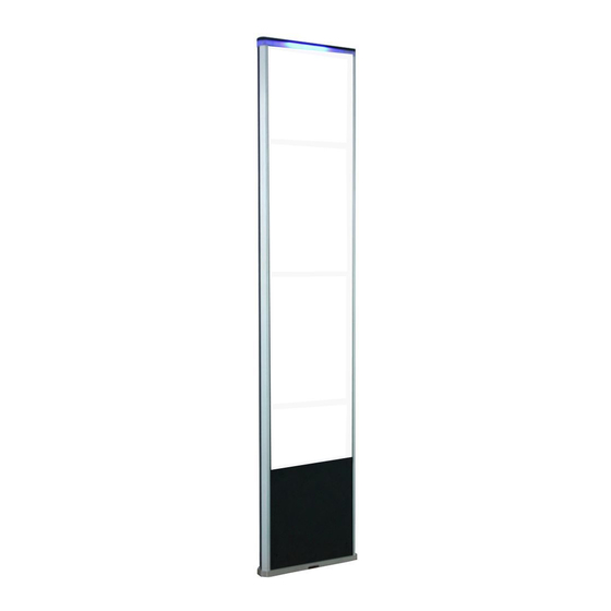
- Page 1 AMTEK 150/250/350/450/750 Operation Manual 58kHz Acousto-Magnetic EAS System valid for AM Pro-Line electronics TX/RX/Mono Hardware Version AMPRO 700 V7.4, Firmware Version AMP 3.1...
-
Page 2: Safety Guidelines
Route the RX-TX cable and power supply cables through places where they cannot be easily damaged! Do not use the system in water condensing conditions! Do not use the system in explosive environmental conditions! AMTEK Version 7.4 2019-01 Page 2 ©Inomatic 2017-2019... - Page 3 Receiver antennas and subsequently trigger an alarm signal. F40 tag Mini Pencil APX (DR) label Super tag II AM Hard Tags and Labels AMTEK Version 7.4 2019-01 Page 3 ©Inomatic 2017-2019...
- Page 4 The system can be automatically switched on/off at certain times. The time for ON and InfoNet OFF can be set via the software. The system will consume much less power during OFF time (Energy saving) AMTEK Version 7.4 2019-01 Page 4 ©Inomatic 2017-2019...
- Page 5 Showing the importance of the alarm (is a customer moving in or out during the alarm) Detecting undefined alarms Pinpoint the exact aisle where the alarm occurred Generate reports on visitor counts and alarm counts AMTEK Version 7.4 2019-01 Page 5 ©Inomatic 2017-2019...
- Page 6 Transmitter Coil Resistance 2 ohm (±5%) Burst Repetition Rate 50Hz (60Hz) Receiver Center Frequency 58 kHz Alarm Audio level 97dBA Environmental Ambient Temperature 0°C to 50°C Relative Humidity 0 to 90% (Non-condensing) AMTEK Version 7.4 2019-01 Page 6 ©Inomatic 2017-2019...
- Page 7 The picture below shows a top view of the Processor board. Table 2.2 lists the board’s relevant connectors and tuning components together with their functions. Matching lower coil Matching upper coil J1 to J6 J7 toJ12 TX1 TX2 Reset Picture 2.1 - Processor board V7.4 top view AMTEK Version 7.4 2019-01 Page 7 ©Inomatic 2017-2019...
- Page 8 The AM Pro-line V7.4 board allows the connection of a two color LED top-light. LED1 (ON LED, active low) LED 2 (Alarm LED, active low) Maximum current for LED1 and LED 2 is 200mA AMTEK Version 7.4 2019-01 Page 8 ©Inomatic 2017-2019...
- Page 9 H17 LAN ok LED blinking H18 LAN ok LED ON Power LEDs H19 12VDC power LED ON H20 5VDC power LED ON H21 3.3VDC power LED ON AMTEK Version 7.4 2019-01 Page 9 ©Inomatic 2017-2019...
- Page 10 In this case, the RX matching can be modified for the upper and lower loop using the rotary switches TW1 and TW2. AMTEK Version 7.4 2019-01 Page 10 ©Inomatic 2017-2019...
- Page 11 RX board (X6) and the other end to the TX board (RC1 or RC2). To avoid noise capturing, the connection between the RX and TX antenna should be as short as possible. AMCTR 710 Connection Cable AMTEK Version 7.4 2019-01 Page 11 ©Inomatic 2017-2019...
- Page 12 18VDC (LED red/blue) L1 L2 L3 L4 Power Processor board 2 50VDC (LED red/blue) 18VDC (LED red/blue) AMPSS 700 V6 power supply If any LED lights “red” means the respective voltage is missing AMTEK Version 7.4 2019-01 Page 12 ©Inomatic 2017-2019...
- Page 13 Always connect the power supply to the system first before switching on the power supply. Always switch off the power supply first before disconnecting the power supply to the system. Local laws and regulations must be respected when installing and servicing this device AMTEK Version 7.4 2019-01 Page 13 ©Inomatic 2017-2019...
- Page 14 The AMPSS 700V6 was designed to power our new AM antenna generation whit AWG 20 antenna wires which require reduced loop voltage. Operating the TX antenna with a higher voltage (> 50VDC) may result in higher matching voltage which can damage the board. AMTEK Version 7.4 2019-01 Page 14 ©Inomatic 2017-2019...
-
Page 15: System Configurations
2.6. System Configurations 2.6.1 Single Mono Antenna (AMPRO 700V7.4 configured as “Mono”) LED light Buzzer output Relay Output LAN Cable AMPSS 700 Single Mono Configuration AMTEK Version 7.4 2019-01 Page 15 ©Inomatic 2017-2019... - Page 16 Multi Mono antenna Configuration The AM power supply V6 allows the connection of up to two AM Processor antennas. Hardware synchronization might be necessary, if 2 or more AM Processor antennas are used. AMTEK Version 7.4 2019-01 Page 16 ©Inomatic 2017-2019...
- Page 17 “Dual and Split system. The following gives a schematic overview about the necessary components and connections for both configurations. RX antenna TX antenna LED light LED light AMCTR 710 Shop -LAN LAN Port AMTEK Version 7.4 2019-01 Page 17 ©Inomatic 2017-2019...
- Page 18 2.) To have the connection between the RX and the TX antenna (AMCTR 710 Connection Cable) as short as possible. Hardware synchronization might only be necessary, if 2 or more TX antennas are used. AMTEK Version 7.4 2019-01 Page 18 ©Inomatic 2017-2019...
-
Page 19: System Installation
Electronic devices, like computers, laptop screens, LCD screens, cash registers, engines, transformers, etc. Vertically positioned power cables, both low voltage and high voltage. Lights (flashing, fluorescent, halogen, gas-de-charge, etc.) Metal scan systems installed in close vicinity. AMTEK Version 7.4 2019-01 Page 19 ©Inomatic 2017-2019... - Page 20 “Earth” of the power supply plug is connected to the power supply socket. Blown fuses shall be replaced with fuses of the same kind. ALWAYS UNPLUG power supply BEFORE CHANGING blown fuses! AMTEK Version 7.4 2019-01 Page 20 ©Inomatic 2017-2019...
- Page 21 Connect Power Supply to AC 230V/50Hz source, switch on the power supply. Connect the computer via the LAN cable and start InfoNet InfoNet V5 software (for tuning please refer to the manual) AMTEK Version 7.4 2019-01 Page 21 ©Inomatic 2017-2019...
- Page 22 Whether “TX OFF function ” is activated by the respective checkbox inside the infoNet infoNet Software (see Manual for further details). De-Activate the TX OFF function if not done yet. The LEDs should light up now. AMTEK Version 7.4 2019-01 Page 22 ©Inomatic 2017-2019...
- Page 23 Wait a while for the capacitors to discharge! High voltage! Function Relevant jumpers Associated LED bar Matching of the upper loop J1 to J6 Matching of the lower loop J7 to J12 AMTEK Version 7.4 2019-01 Page 23 ©Inomatic 2017-2019...
- Page 24 To measure the voltage the antenna loops need to be connected. The infoNet V5 will show if the matching results in too high Voltage. Oscilloscope setting V =500V T= 20ms Board Ground (GND) AMTEK Version 7.4 2019-01 Page 24 ©Inomatic 2017-2019...
- Page 25 If you have to tune the inductor CS1 please do it carefully with a non-metal screw driver, otherwise you might damage the ferrite core. infoNet For detailed description of the RX tuning refer to the Manual. AMTEK Version 7.4 2019-01 Page 25 ©Inomatic 2017-2019...
- Page 26 TX Pulse 11.7ms 20ms 10ms 1.6ms or 1.5ms (setting via InfoNet) TX Pulse Signal window 1400μs Reference window 1400μs Detect delay 100μs The LS2 can be shifted individually via infoNet V5 or higher AMTEK Version 7.4 2019-01 Page 26 ©Inomatic 2017-2019...
- Page 27 Two AM systems that are properly synchronized SYSTEM 1 SYSTEM 2 If two or more AMTEK Processor antenna are connected to the same main power phase they would not need to be synchronized by either hardware or software. AMTEK Version 7.4 2019-01 Page 27 ©Inomatic 2017-2019...
- Page 28 Please note that any TX pulse should also not fall into to the Reference window LS 2 as it would push up the noise level of the system dramatically. The system may not alarm but the performance will be affected. AMTEK Version 7.4 2019-01 Page 28 ©Inomatic 2017-2019...
- Page 29 2.) The hardware synchronization ports (LAN 1 or LAN 2) must be connected with a shielded LAN cable. The picture below illustrates the connection and the necessary settings for Master or Slave operation. Master Processor antenna Slave Processor antenna Shielded LAN cable AMTEK Version 7.4 2019-01 Page 29 ©Inomatic 2017-2019...
- Page 30 Synchron value of all connected slave antennas. Please do not turn on the power before the configuration is ready. First switch on the power supply for the “Slave” antenna and then the power supply to the “Master” antenna. AMTEK Version 7.4 2019-01 Page 30 ©Inomatic 2017-2019...
- Page 31 Slave 1 Other Slaves Last Slave Shop-LAN (if required) Installation of 5 Processor Antennas Hardware Sync/LAN Sysync. The new Dual power supply AMPSS 700V6 50VDC allows the connection of two Processor antennas. AMTEK Version 7.4 2019-01 Page 31 ©Inomatic 2017-2019...
-
Page 32: Lan Connection
Visitor counter analysis (if equipped with integrated visitor counter module) infoNet For more set-up information please refer to the V5 software manual Connection of 1 Processor Antenna Shop LAN Connection of 2 or more Processor Antennas Shop LAN AMTEK Version 7.4 2019-01 Page 32 ©Inomatic 2017-2019... -
Page 33: Regulatory Compliance
Electronic equipment that will be sold or put into service for the first time, anywhere in the European community. It proves to the buyer and user that this product meets all essential safety and environmental requirements as they are defined in the “European Directives”. AMTEK Version 7.4 2019-01 Page 33 ©Inomatic 2017-2019...
Need help?
Do you have a question about the AMTEK Series and is the answer not in the manual?
Questions and answers