Advertisement
STM Series -
Applications
The STM Series Flanged Ball Valves are designed to
regulate hot and chilled water, 50/50 glycol solutions,
and 25 psig steam in Heating, Ventilating, and Air
Conditioning (HVAC) systems.
IMPORTANT: The STM Series Flanged Ball Valves are intended
to control saturated steam, hot water, and chilled water flow
under normal equipment operating conditions. Where failure or
malfunction of the valve could lead to personal injury or pro
perty damage to the controlled equipment or other property,
additional precautions must be designed into the system. In-
corporate and maintain other devices, such as supervisory or
alarm systems or safety or limit controls, intended to warn of or
protect against failure or malfunction of the valve.
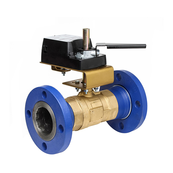
Installation
Install the STM Series Flanged Ball Valves with the actua-
tor at or above the centerline of the horizontal piping, as
shown in Figure 1.
IMPORTANT: In steam applications, install the valve with the
stem horizontal to the piping. Failure to follow these guidelines
may shorten the life of the actuator.
To minimize heat transfer in steam applications, wrap the
valve and piping with insulation.
Allow at least 4 in. (102 mm) of clearance from the top of
the shaft to remove the actuator (as noted in dimensions).
Flanged Characterized Ball Valves
Figure 1: Recommended Mounting Positions for Non-Steam Applications
—
Installation Instructions
When mounting the actuator in the field and before
installing the actuator, use an adjustable wrench to man-
ually rotate the valve stem several times. This rotation
breaks the torque that may have built up during long-
term storage.
IMPORTANT: Do not attempt to manually rotate the drive
shaft while the actuator is installed without first releasing the
actuator gears. Manually rotating the drive shaft without
releasing the actuator gears may result in permanent damage
to the actuator.
IMPORTANT: Take care to prevent foreign material such as weld
slag, thread burrs, metal chips, and scale from entering the
piping system. This debris can damage or severely impede the
operation of the valve by embedding itself in the seats, scor-
ing the valve, and ultimately resulting in seat leakage. If the
debris becomes embedded in the seats, subsequent flushing and
filtering of the piping system with the valve installed does not
remedy the problem.
A
1
Bray Controls Commercial Division
13788 West Road, Suite 200A
Houston, Texas 77041
BCDSales@Bray.com
Phone: 1-888-412-2729
Fax: 1-888-412-2720
www.braycommercialdivision.com
AB
01/30/19
Advertisement
Table of Contents

Related Manuals for Bray Controls STM Series

Summary of Contents for Bray Controls STM Series
- Page 1 Installation ing the valve, and ultimately resulting in seat leakage. If the Install the STM Series Flanged Ball Valves with the actua- debris becomes embedded in the seats, subsequent flushing and tor at or above the centerline of the horizontal piping, as filtering of the piping system with the valve installed does not shown in Figure 1.
- Page 2 STM Series - — Flanged Characterized Ball Valves Installation Instructions Continued - 2-Way Dimensions 2-Way STM Dimensions Flow Coefficient Bolt Hole Number of Size Weight Valve Models in.(mm) Diameter Bolt Holes lbs. STM 250-2-47 40.7 2.05 5.50 3.50 5.71 11.42 10.25...
- Page 3 STM Series - — Flanged Characterized Ball Valves Installation Instructions Continued - 3-Way Dimensions 3-Way STM Dimensions Size Flow Coefficient Bolt Hole Number of Weight Valve Models in.(mm) Diameter Bolt Holes lbs. STM 250-3-47 40.7 5.50 3.50 5.71 11.42 10.25 2.05...
- Page 4 STM Series - — Flanged Characterized Ball Valves Installation Instructions Continued - Mounting Location Considerations Piping IMPORTANT: Protect the actuator from dripping Be sure to wire the input lines to the electric actuator water, condensation, and other moisture. Water or correctly for the valve to move in the proper direction.
- Page 5 CCW position while a maximum control signal Two-way STM Series Ball Valves are fully open drives the electric actuator in the fully CW position. when the electric actuator is fully Counterclockwise...
Need help?
Do you have a question about the STM Series and is the answer not in the manual?
Questions and answers