Table of Contents
Advertisement
Quick Links
Advertisement
Table of Contents

Summary of Contents for Cooper Tools Cleco TME-111
- Page 1 Artisan Technology Group is your source for quality new and certified-used/pre-owned equipment SERVICE CENTER REPAIRS WE BUY USED EQUIPMENT • FAST SHIPPING AND DELIVERY Experienced engineers and technicians on staff Sell your excess, underutilized, and idle used equipment at our full-service, in-house repair center We also offer credit for buy-backs and trade-ins •...
- Page 2 Programming Manual PL12-1300 12/00 Cleco Electric Tool Control TME-100 Series Reference Document: PL12-1400 Parts Manual For additional product information visit our website at http://www.coopertools.com A M E R I C A S E U R O P E CooperTools Cooper Power Tools GmbH & Co. P.O.
- Page 3 Without the express approval of Cooper Tools this document must not be reproduced in its entirity or in part by any means; it must not be converted to any type of natural or machine readable language or be saved on data storage media of electronic, mechanic, optical or other type.
-
Page 4: Table Of Contents
Electric Tool Control TME-100 Series Cleco Contents Page Getting Started Safe Work Practices Symbol ..............5 Checking Your Unit................5 Software ....................5 Installing Unit ..................5 1.4.1 General....................5 1.4.2 Mounting....................6 1.4.3 Location Considerations ............... 6 1.4.4 Source Power ..................6 Connecting Unit .................. - Page 5 Electric Tool Control TME-100 Series Cleco 3.3.4 Standard Application Builder / Advanced Parameters ......31 3.3.5 Advanced Application Builder / Application Matrix ......32 3.3.6 Advanced Application Builder / Inputs..........33 3.3.7 Advanced Application Builder / Outputs..........34 3.3.8 Advanced / System Settings ............... 36 RUN Screen ..................
-
Page 6: Getting Started
Electric Tool Control TME-100 Series Cleco Getting Started Safe Work Practices Symbol The signal word "Warning" identifies all notes on safe work practices in this operating instruction, alerting to hazards for life and health of people. Observe these notes and pro- ceed with special care in the cases described. -
Page 7: Mounting
Electric Tool Control TME-100 Series Cleco 1.4.2 Mounting Each unit is used primarily as a single tool process/controller/monitor installed in a work station or work area. It may be wall mounted, table mounted, beam mounted, suspended overhead, pedestal mounted or used without mounting. Always choose a stable location to avoid the possi- bility of unit damage and/or operator injury through hitting, falling, vibration or inconvenient mounting. -
Page 8: Energizing Unit
Electric Tool Control TME-100 Series Cleco Energizing Unit To avoid the hazard of electrical shock or burn the following instructions must be adhered to. Failure to follow these instructions may also cause damage to your unit and void existing warranties. Upon application of power, the unit will initiate a self test. - Page 9 Electric Tool Control TME-100 Series Cleco After the Navigator Menu is displayed, verify the Tool Memory by entering Tool Setup. If Tool Memory is not active then select a tool using the Tool Library. Press the ship's wheel to return to the Navigator Menu.
-
Page 10: Attachment A.1
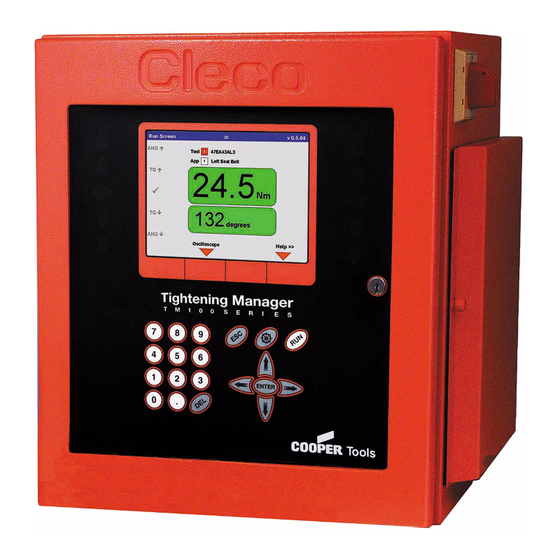
Electric Tool Control TME-100 Series Cleco Attachment A.1 Mounting Bracket Sidedoor Assembly Display Connector Indicator (see detail Lights below) Keypad Double-Bit Enclosure Fig. 1-3: Controller Power Switch Tool Connector I/O Outputs Floppy Drive I/O Inputs Printer Power Out Serial Ports (2) Printer Port Power In Keyboard Port... - Page 11 Electric Tool Control TME-100 Series Cleco PL12-1300 12/00 en01d141.fm, 30.01.2001 Artisan Technology Group - Quality Instrumentation ... Guaranteed | (888) 88-SOURCE | www.artisantg.com...
-
Page 12: Controller Specifications
Electric Tool Control TME-100 Series Cleco Controller Specifications Understanding the Keypad The following is a brief explanation of the keypad keys. You will need to become familiar with these keys so you can smoothly program your unit. Soft Keys (F1-F4) - used to select functions based on the screen displayed. -
Page 13: Specifications
Electric Tool Control TME-100 Series Cleco Specifications 2.2.1 Enclosure Model Weight* Width Height Depth TME-111 36.4 16.5 419.1 17.5 444.5 12.3 312.4 * Mounting plate adds weight of 7 lbs / 3.2 kg and depth of 1.62 in / 41.1 mm •... -
Page 14: Keypad Overlay
Electric Tool Control TME-100 Series Cleco 2.2.3 Keypad Overlay Key Definitions Description Numbers 0-9 Decimal point Delete Escape Navigator Menu Run Screen Up Arrow Down Arrow Left Arrow Right Arrow ENTER Enter Orange Border 4 Soft Keys 2.2.4 Indicators 5 Highly visible indicators •... -
Page 15: Internal Ac Input Power
Electric Tool Control TME-100 Series Cleco Arcnet PC/104 board • Arcnet communication • 4 +24 V inputs • 12 +24 V outputs • 24-position keypad decoder • Battery-Backed SRAM, 1 MB External I/O PC/104 board • 8 optically isolated inputs •... - Page 16 Electric Tool Control TME-100 Series Cleco Tool Pin # Description Value +Excitation +12 V +/- .05 V -Excitation Drehmomentsignal 0 to +5 V 0 V Drehmomentsignal Tool Memory TXD - -3 V to +3 V Tool Memory TXD + -3 V to +3 V Tool Memory RXD - -3 V to +3 V Tool Memory RXD +...
- Page 17 Electric Tool Control TME-100 Series Cleco Serial -25 V to +25 V -25 V to +25 V Parallel Pin # Description Value Strobe 0 to +5 V Data 0 0 to +5 V Data 1 0 to +5 V Data 2 0 to +5 V Data 3 0 to +5 V...
- Page 18 Electric Tool Control TME-100 Series Cleco Inputs Pin # Description Value +24 V (Output) +24 VDC Input 0 0 to +24 V Input 1 0 to +24 V Input 2 0 to +24 V Input 3 0 to +24 V Input 4 0 to +24 V Input 5...
- Page 19 Electric Tool Control TME-100 Series Cleco PL12-1300 12/00 en02d141.fm, 30.01.2001 Artisan Technology Group - Quality Instrumentation ... Guaranteed | (888) 88-SOURCE | www.artisantg.com...
-
Page 20: Programming
Electric Tool Control TME-100 Series Cleco Programming Navigator Menu c00277en.bmp Fig. 3-1: Navigator Menu 3.1.1 Basic Navigation Instructions Each field in a screen is selectable with an orange highlight using the 4 arrow keys and Enter. Upon entering a screen the top left most field is always highlighted. The Navigator key (ship's wheel) will always return the user to the Navigator Menu. -
Page 21: Navigator Menu
Electric Tool Control TME-100 Series Cleco 3.1.3 Navigator Menu Basic Application Builder Basic Application Builder allows the user to graphically select and program a two-stage rundown for Torque Control/Angle Monitor (Sequence 11/Sequence 30) or Angle Control/Torque Monitor (Sequence11/Sequence 50) for any of the 8 Applications. The user only enters Torque, Angle, and Speed Setpoints in one screen. -
Page 22: Basic Application Builder
Electric Tool Control TME-100 Series Cleco Administration From the Administration screen the user can load, save and configure system information. Administration functions include loading and saving the system parameters to a diskette, setting date and time, setting password protection, and printing the system parameters. Basic Application Builder c00278en.bmp Fig. -
Page 23: Basic Parameters For Torque Control / Angle Monitor
Electric Tool Control TME-100 Series Cleco Fastening Strategies Torque Control/Angle Monitoring (Sequence 11/Sequence 30) or Angle Control/Torque Monitoring (Sequence 11/Sequence 50) are selectable from the dropdown list- box in the upper right hand corner of the screen. Once a Strategy is selected, the appropriate Parameters will be displayed for programming. -
Page 24: Basic Application Builder Parameters
Electric Tool Control TME-100 Series Cleco 3.2.3 Basic Application Builder Parameters Parameter Name Range Default Fastening Strategy Torque Control/Angle Monitor Torque Control/Angle Monitor Angle Control/Torque Monitor Trigger Torque [Nm] 0 to Tool Max Turnoff Torque Stage 1 [Nm] 0 to Tool Max Threshold Torque [Nm] 0 to Tool Max Torque Low Limit [Nm]... -
Page 25: Standard Application Builder
Electric Tool Control TME-100 Series Cleco Standard Application Builder 3.3.1 Standard Application Builder / View Stages c00280en.bmp Fig. 3-4: View Stages From View Stages, Stages 1-6 and a Backoff Stage are programmable for a given tool and appli- cation. When the tool is started, each Stage having a programmed Fastening Sequence will be run in succession based on the results from the previous stage. -
Page 26: Standard Application Builder / Select Sequence
Electric Tool Control TME-100 Series Cleco 3.3.2 Standard Application Builder / Select Sequence c00281en.bmp Fig. 3-5: Select Sequence Fastening Sequences are selectable for a given Tool, Application and Stage by using the Control and Monitor check boxes or selecting a Fastening Sequence directly from the dropdown listbox. The following Fastening Sequences or Fastening Strategies are available: Sequence 11 High Speed Rundown... - Page 27 Electric Tool Control TME-100 Series Cleco The following table shows a matrix of the Control and Monitor schemes for each Sequence: Sequence 11 Sequence 30 Sequence 50 Sequence 41 Control Torque Control Angle Control Yield Control Torque Control Reverse Angle Control Reverse Monitor Torque Monitor Angle Monitor...
-
Page 28: Standard Application Builder / Parameters
Electric Tool Control TME-100 Series Cleco tion. When the trigger torque is reached the torque curve is recorded and can be viewed and evaluated using the oscilloscope function. Sequence 41 Angle Controlled Back-off with Angle Monitoring This fastening sequence is generally used to loosen a bolt a specified number of degrees. The resolver integrated into the nutrunner measures the angle during the untightening. - Page 29 Electric Tool Control TME-100 Series Cleco the trigger torque is reached the torque curve is recorded and can be viewed and evaluated using the oscilloscope function. The following parameters are programmable from the Standard Application Builder: • Fastening Sequence = 11 •...
- Page 30 Electric Tool Control TME-100 Series Cleco Parameter Name Range Default Turnoff Torque [Nm] Low Limit to Tool Max Torque High Limit [Nm] Turnoff to 9999 Angle Low Limit [Deg] 0 to 9999 Angle High Limit Low Limit to 9999 Speed [RPM] 0 to Tool Max Sequence 50 Angle Controlled Tightening with Angle and Torque Monitoring...
- Page 31 Electric Tool Control TME-100 Series Cleco Sequence 41 Angle Controlled Back-off with Angle Monitoring This fastening sequence is generally used to loosen a bolt a specified number of degrees. The resolver integrated into the nutrunner measures the angle during the untightening. The value is processed by the control system.
-
Page 32: Standard Application Builder / Advanced Parameters
Electric Tool Control TME-100 Series Cleco The backoff parameters that are not displayed are set to values as in the table below. Parameter Name Sequence 41 Sequence 46 Start delay time [mS] Start spike time [mS] Max. Fastening time [mS] 10000 10000 End delay time [mS]... -
Page 33: Advanced Application Builder / Application Matrix
Electric Tool Control TME-100 Series Cleco Advanced Parameters • Start delay time [mS] = time delay before the stage will start. • Start spike time [mS] = time delay for the control system to start measuring torque after the stage starts. •... -
Page 34: Advanced Application Builder / Inputs
Electric Tool Control TME-100 Series Cleco 3.3.6 Advanced Application Builder / Inputs c00285en.bmp Fig. 3-9: Inputs c00288en.bmp Fig. 3-10: Input Timing Diagram PL12-1300 12/00 en03d141.fm, 30.01.2001 Artisan Technology Group - Quality Instrumentation ... Guaranteed | (888) 88-SOURCE | www.artisantg.com... -
Page 35: Advanced Application Builder / Outputs
Electric Tool Control TME-100 Series Cleco Eight optically isolated, +24V inputs are available at the Phoenix input connector under the right side door and are defined as follows: Inputs 0-2 Application Select 0-2: Application Selects 0-2 are used to select Applications 1-8 using a binary count of 0-7 where Applicaton Select 0 is the least significant bit. - Page 36 Electric Tool Control TME-100 Series Cleco c00287en.bmp Fig. 3-12: Output Timing Diagram Eight relay outputs are availiable at the Phoenix output connector under the right side door and are defined as follows: Output 0 Cycle OK: Active if Torque/Angle/Yield are within programmed limits. Output 1 Cycle NOK: Active if Torque/Angle/Yield are outside limits or some other error has occurred.
-
Page 37: Advanced / System Settings
Electric Tool Control TME-100 Series Cleco 3.3.8 Advanced / System Settings c00313en.bmp Fig. 3-13: System Settings The System Settings allows the user to assign the System a name and number as well as change the system torque units. The torque units can be set to Nm, Ft-Lb, In-Lb, or Kg-cm. When the units are changed, all torque values are immediately changed to the new units RUN Screen c00289en.bmp... -
Page 38: Oscilloscope
Electric Tool Control TME-100 Series Cleco will be red if the value is too high, yellow if it is too low, and green if it is within limits. The current tool model number, application name, and indicator labels are also displayed. The desired Application (1-8) is selectable using the keypad. -
Page 39: Communication
Electric Tool Control TME-100 Series Cleco Rundown Indicator At the bottom left of the display is the rundown indicator. The final torque and angle values are displayed on either a green (OK) background or red (NOK) background. Parameters At the bottom of the display is a summary of the parameter settings for the rundown. The Save softkey (F2) lets you print a hardcopy. -
Page 40: Communications / Serial Data Transmission
Electric Tool Control TME-100 Series Cleco 3.6.2 Communications / Serial Data Transmission c00292en.bmp Fig. 3-17: Data Transmission The Serial Data Transmission is sent after each cycle to the programmed COM port. The Basic settings are Port, Baud rate, Data bits, Stop bits, Parity, and Protocol. The following table details the transmission data: Start Length or Value... -
Page 41: Tool Setup
Electric Tool Control TME-100 Series Cleco Start Length or Value Description 1 Char ASCII Status Overall Status Flag A = accept R = reject 2 Digit ASCII Batch Count (Only for Batch Count) 2 Digit ASCII Batch Size (User programmable) (Advances only on ACCEPT) 0D hex CR (carriage return) -
Page 42: Tool Library
Electric Tool Control TME-100 Series Cleco Pressing the Tool Library (F1) key will allow the user to select from a library of predefined tools. This library can be used to program the tool parameters when tool memory is not available or to change the existing tool memory values. -
Page 43: Tool Library / Custom
Electric Tool Control TME-100 Series Cleco 3.8.2 Tool Library / Custom c00295en.bmp Fig. 3-20: Custom Tool Tools will be added to the Custom Tool Library when a tool that does not exist in the Tool Library is used. Anytime data is entered in the Tool Setup screen that does not match data in the Stan- dard Tool Library, the new tool will be added to the Custom Tool Library. -
Page 44: Statistics
Electric Tool Control TME-100 Series Cleco Statistics 3.9.1 Statistics / Summary c00296en.bmp Fig. 3-21: Statistical Summary The user can view the Statistical Summary for the selected rundowns of any Tool or Application. This summary includes high value, low value, range, average, standard deviation, and CpK for Torque and Angle. -
Page 45: Diagnostics
Electric Tool Control TME-100 Series Cleco The user can view the Chronological History for the selected rundowns of any Tool or Applica- tion. This history includes time, date, status, torque, and angle. The Clear Chrono (F3) soft key allows the user to delete all rundowns. 3.10 Diagnostics 3.10.1... -
Page 46: Tool / Calibration
Electric Tool Control TME-100 Series Cleco 3.10.2 Tool / Calibration c00299en.bmp Fig. 3-24: Tool / Calibration This test function cyclically recalibrates the system with the values used immediately before the start of a rundown. The must be released for this function! The values "Calibration offset" and "Calibration voltage"... -
Page 47: Tool / Voltages
Electric Tool Control TME-100 Series Cleco 3.10.3 Tool / Voltages c00300en.bmp Fig. 3-25: Tool / Voltages The table displays the measured voltages of a channel. These are the most important supply voltages on the measuring board, required for proper torque and angle measurement. Therefore, these must be monitored continuously. If a voltage is out of tolerance, it is shown in red. -
Page 48: Tool / Angle Encoder
Electric Tool Control TME-100 Series Cleco 3.10.4 Tool / Angle Encoder c00301en.bmp Fig. 3-26: Tool / Angle Encoder The tool start switch starts the spindle with a speed of 30 % of the maximum. After one revolu- tion of the output shaft (set angle 360 deg), measured with the tool resolver, it is stopped. During a permanently adjusted dwell time of 200 ms any further angle pulses occurring are traced. -
Page 49: Tool / Tq Measurement
Electric Tool Control TME-100 Series Cleco 3.10.5 Tool / TQ Measurement c00302en.bmp Fig. 3-27: Tool / TQ Measurement This test function recalibrates the system with the values used immediately before the start of a rundown. The spindle must therefore be released still when this function is called up! Then the tool is started at zero speed and the torque is continuously measured and displayed. -
Page 50: Arcnet / Map
Electric Tool Control TME-100 Series Cleco since the integrated speed measurement is derived from the resolver signals. When you release the start switch the spindle stops. As a safety function the torque is monitored by the tool trans- ducer. If it exceeds 15 % of its calibrated value, the tachometer function is terminated. 3.10.7 Arcnet / Map c00303en.bmp... -
Page 51: Arcnet / Statistic
Electric Tool Control TME-100 Series Cleco 3.10.8 Arcnet / Statistic c00304en.bmp Fig. 3-30: Arcnet / Statistic The ARCNET statistics allow to check the stability of the field bus system. There are two differ- ent statistics: • For all external hardware components (bridges, TMs) •... - Page 52 Electric Tool Control TME-100 Series Cleco Host Driver Statistics Reconfiguration Change upon each reset of a participant Host reconfiguration Change upon each reset or severe failure CRC error Should be stable Outbound packets - Inbound packets - Next ID Change upon switch-off/on of downstream participant Excessive NAK Should be stable Lost Token...
-
Page 53: Serial
Electric Tool Control TME-100 Series Cleco 3.10.9 Serial c00305en.bmp Fig. 3-31: Serial Port Diagnostics The serial diagnostics allows the user to test the selected COM port by displaying sent (blue text) and received data (red text). The Start Hardware Test (F1) soft key will send ten bytes and toggle the TXD line. It will read back the bytes based on the RXD signal. -
Page 54: Utilities
Electric Tool Control TME-100 Series Cleco 3.11 Utilities 3.11.1 Utilities / Update Software c00306en.bmp Fig. 3-32: Update Controller Software Using the radio buttons the user can select either the TME or just the Tightening Module itself. The current installed versions are listed for each module. As the software is updated a progress bar will be displayed. -
Page 55: Administration
Electric Tool Control TME-100 Series Cleco 3.12 Administration 3.12.1 Administration / Load/Save c00313en.bmp Fig. 3-33: Load / Save Using the check boxes, the user can select the parameters to load or save to the floppy diskette. The Load from Floppy (F2) soft key will search the floppy for the selected parameters and update them accordingly. -
Page 56: Administration / Print
Electric Tool Control TME-100 Series Cleco 3.12.2 Administration / Print c00308en.bmp Fig. 3-34: Print Using the check boxes, the user can select the parameters to print. These will be sent to the printer defined in the Communications setup or to a file on the floppy diskette if selected. The Cancel Print (F2) soft key will cancel the print job immediately. -
Page 57: Administration / Date & Time
Electric Tool Control TME-100 Series Cleco last entry changes automatically when parameters are changed. The Password function sup- ports up to ten different users plus a master password. Pressing Add User (F1) it is possible to add a new user. If the first user does not activate the "Administration"... -
Page 58: Statistics
Electric Tool Control TME-100 Series Cleco Statistics Understanding Statistics Your unit provides a wide array of statistical and data reports (charts) for the control of manufac- turing processes. The following provides a description of the control chart for variables and an outline of the procedure for its use. -
Page 59: The Procedure
Electric Tool Control TME-100 Series Cleco from the average increases. Since the shape resembles a bell, it is sometimes referred to as a bell curve. The normal curve is defined by two conditions - the average of all items produced, and the amount of variation from the average. - Page 60 Electric Tool Control TME-100 Series Cleco Designate the Sample Frequency Selection of the sample frequency should be based on economic considerations for the cost of measurements and the potential loss that may occur if samples are not taken often enough. Early in the production run, samples should be taken more frequently and then extended after satisfactory control is verified.
- Page 61 Electric Tool Control TME-100 Series Cleco Calculate Process Center Lines After data for 20 samples of five have been plotted, calculate the center lines for both the aver- age and range plottings. The center line for the average chart is known as the grand average ( ) and is the average of all of the sample averages.
- Page 62 Electric Tool Control TME-100 Series Cleco Sometimes a process takes time to stabilize after start-up. If the indication of special cause vari- ation occurs only in the first few samples, continue to take several more samples and recalculate the limits by omitting the special cause values. However, if the indications of special cause vari- ation occur other than at start-up, action should be taken to identify and correct the cause, and the process re-started.
-
Page 63: System Improvement
Electric Tool Control TME-100 Series Cleco calculating the average or range for a sample, and plotting a point on the control chart incor- rectly. Special cause variation may be indicated by one of the following situations: • A point outside a control limit. •... -
Page 64: Statistic Symbols
Electric Tool Control TME-100 Series Cleco Statistic Symbols • σ standard deviation (or sigma) • mean (or average) • range • Capability of Process • Capability index • number of runs • Sub Sz= Subgroup size • Torque summary run data •... - Page 65 Electric Tool Control TME-100 Series Cleco PL12-1300 12/00 en04d141.fm, 30.01.2001 Artisan Technology Group - Quality Instrumentation ... Guaranteed | (888) 88-SOURCE | www.artisantg.com...
-
Page 66: Glossary
Electric Tool Control TME-100 Series Cleco Glossary accepted data data that fall within the acceptable limits in a fastening strategy accepted rundown a run cycle within limits angle capability indexes a measure of acceptable variation of final angle values in a fastening process angle control a fastening strategy by which you are controlling a tool by... - Page 67 Electric Tool Control TME-100 Series Cleco control parameters the parameters that define the fastening strategy sequence for a given tool cycle complete active whenever tool is not running cycle NOK active if torque/angle/yield are outside limits or some other error has occurred cycle OK active if torque/angle/yield are within programmed limits cycle start switch...
- Page 68 Electric Tool Control TME-100 Series Cleco port the socket used for connecting a cable or peripheral equipment power supply a unit used to supply power to an electrical device pulses per degree number of encoder pulses generated by the tool when rotating the head exactly 1 degree or 1/360 of a revolution range (R) a statistical measurement of the difference between the...
- Page 69 Electric Tool Control TME-100 Series Cleco synchronization input when active allows the tool to start from stage to stage in conjunction with tool start synchronization output active at the end of each stage to signal a stage is com- plete threshold torque [Nm] torque to begin counting angle tool enable...
- Page 70 Artisan Technology Group is your source for quality new and certified-used/pre-owned equipment SERVICE CENTER REPAIRS WE BUY USED EQUIPMENT • FAST SHIPPING AND DELIVERY Experienced engineers and technicians on staff Sell your excess, underutilized, and idle used equipment at our full-service, in-house repair center We also offer credit for buy-backs and trade-ins •...
Need help?
Do you have a question about the Cleco TME-111 and is the answer not in the manual?
Questions and answers