Advertisement
OPERATING INSTRUCTIONS MANUAL
(Please retain for future reference)
For
FVO-1100TR INDIRECT FIRED HEATER TRAILER
CERTIFIED FOR USE IN CANADA AND U.S.A.
As per CSA B140.8 Portable Oil Fired Heaters / CSA B140.0 2003 Oil Burning Equipment
UL733 Oil Fired Air Heaters
Construction Heaters Unattended Type.
FLAGRO INDUSTRIES LIMITED
ST. CATHARINES, ONTARIO
CANADA
Advertisement
Table of Contents

Related Manuals for Flagro FVO-1100TR


Summary of Contents for Flagro FVO-1100TR
- Page 1 OPERATING INSTRUCTIONS MANUAL (Please retain for future reference) FVO-1100TR INDIRECT FIRED HEATER TRAILER CERTIFIED FOR USE IN CANADA AND U.S.A. As per CSA B140.8 Portable Oil Fired Heaters / CSA B140.0 2003 Oil Burning Equipment UL733 Oil Fired Air Heaters Construction Heaters Unattended Type.
- Page 2 GENERAL HAZARD WARNING: FAILURE TO COMPLY WITH THE PRECAUTIONS AND INSTRUCTIONS PROVIDED WITH THIS HEATER, CAN RESULT IN DEATH, SERIOUS BODILY INJURY AND PROPERTY LOSS OR DAMAGE FROM HAZARDS OF FIRE, EXPLOSION, BURN, ASPHYXIATION, CARBON MONOXIDE POISONING, AND/OR ELECTRICAL SHOCK. ONLY PERSONS UNDERSTAND...
-
Page 3: Table Of Contents
TABLE OF CONTENTS Trailer Check List…………………………………………………… 4 Towing Instructions…………………………………………………. 5 FVO-1100TR Set-up Procedure……………………………………..6 Set-up Procedure (High Altitude)…………………………………...7,8,9 Nozzle Placement……………………………………………………. 10 Specifications……..………………………………………………….. 11 Trailer Preparation…………………………………………………. 12,13 Heater Start up……………………………………………………… 14 Troubleshooting…………………………………………………….. 15 Heater Maintenance………………………………………………… 16 Feeler Gauge………………………………………………………… 17 Burner Wiring Diagram……………………………………………. 18 Electrode &... -
Page 4: Trailer Check List
TRAILER CHECK LIST PLEASE PERFORM THE FOLLOWING STEPS TO YOUR FVO-1100TR HEATER TRAILER TO ENSURE PROPER OPERATION. • Visually inspect outside & inside of trailer to ensure all instructions and decals are in place and legible. Inspect the tires to ensure road worthy and have proper inflation. -
Page 5: Towing Instructions
TOWING INSTRUCTIONS Before towing the FVO-1100TR, please make sure you go over the following steps to ensure your trailer is road ready. 1. Hitch is securely attached to towing vehicle. 2. Safety chains are securely attached to towing vehicle. 3. Front jack is completely retracted. -
Page 6: Fvo-1100Tr Setup Procedure
FVO-1100TR SETUP PROCEDURE The two FVO-400RC heaters in the trailer need to be tested and set up before every operation. Proper combustion must be achieved using a certified combustion analyzer and smoke gun tester to ensure optimum set up. The air adjustment should be made to achieve a maximum of 10% CO and No. -
Page 7: Setup Procedure (High Altitude)
SETUP PROCEDURE (HIGH ALTITUDE) When the FVO-1100TR is required to operate over 2000 feet above sea level there will be necessary adjustments needed to burn efficiently with thinner air. Please review the following chart as a starting point; please note that a combustion analyzer & smoke gun will be required to achieve optimum set up. - Page 8 INSERTION / REMOVAL OF DRAWER ASSEMBLY To remove drawer assembly, loosen SCREW (3), then unplug CONTROL BOX (1) by carefully pulling it back and then up. Remove the AIR TUBE COVER PLATE (5) by loosening the two retaining SCREWS (4). Loosen SCREW (2), and then slide the complete drawer assembly out of the combustion head as shown.
-
Page 9: Nozzle Placement
NOZZLE PLACEMENT Remove the NOZZLE ADAPTER (2) from the DRAWER ASSEMBLY by loosening the SCREW (1). Insert the proper NOZZLE into the NOZZLE ADAPTER and tighten securely (Do not over tighten). Replace adapter, with nozzle installed, into drawer assembly and secure with screw (1). -
Page 10: Specifications
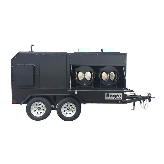
SPECIFICATIONS Model …………………………… FVO-1100TR Input ……………………………... 390,000 BTU x 2 @ 2.61 GPH Engine …………………………… Kubota Liquid Cooled Diesel Electric start/ glow plugs Battery charging alternator Heavy duty Radiator & Air Cleaner Remote Oil Drain Generator………………………… 8 kw @ 1800 rpm (15.4 HP) -
Page 11: Trailer Preparation
TRAILER PREPARATION FOR START-UP PLEASE REVIEW TRAILER CHECKLIST, FVO-1100TR SETUP & GENERATOR MANUAL BEFOR PROCEEDING OPEN REAR GENERATOR ACCESS DOORS OPEN HEATER OUTLET DOOR... - Page 12 INSPECT FUEL GAUGE FOR SUFFICIENT LEVEL OF FUEL MAKE SURE BATTERY LOCK OUT IS TURNED OFF, AND TURN KEY ON CONTROL PANEL TO START OPEN HEATER DOORS & START UP HEATERS...
-
Page 13: Heater Start Up
HEATER START UP INSTRUCTIONS: Open heater inlet doors; verify that each heater toggle “switch” is in the “OFF” position. Attach ducting to outlet duct adapters, if required Start generator Start heaters by moving the toggle switch to “MANUAL” position for manual control. - Page 14 IF HEATER FAILS TO START: Press manual reset button at rear of burner. (Red button) Check fuel level gauge for sufficient amount of fuel. Make sure there are no air blocks in fuel lines or filter. Bleed lines if required. Ensure power supply plug is connected properly.
- Page 15 MAINTENANCE: 1. Every construction heater should be inspected before each use, and at least annually by a qualified service person. Incorrect maintenance my result in improper operation of the heater and serious injury could occur. 2. The hose assemblies shall be visually inspected prior to each use of the heater.
-
Page 16: Feeler Gauge
TEMPERATURE FEELER GAUGE ADJUSTMENT (ATTACHED TO FAN SWITCH) The temperature feeler gauge is required to be always touching the heater exchanger. The temperature feeler gauge controls the air flow over the fan switch, which eliminates any unnecessary fan cycling. The temperature feeler gauge can be adjusted for different outside temperatures, by rotating the location of the temperature feeler gauge holes. -
Page 17: Burner Wiring Diagram
BURNER WIRING DIAGRAM ELECTRICAL CONNECTIONS It is advisable to leave the control box off the sub-base while completing the electrical connections to the burner. - Page 18 ELECTRODE SETTING OIL LINE CONNECTIONS Note: Pump pressure must be set at time of burner start-up. A pressure gauge is attached to the PRESSURE PORT (8) for pressure readings. Two PIPE CONNECTORS (5) are supplied with the burner for connection to either a single or a two-pipe system.
-
Page 19: Parts List
FVO-1100TR – PARTS LIST HARDWARE DOOR LATCH BOLT ON HINGE FMA-2312 FV-450TR PUSH TO CLOSE LOCKING DOOR LATCH/ ROD BALL HITCH FV-443TR FV-465TR FVO-437TR SUPPORT JACK EMERGENCY BREAKAWAY KIT PINTLE HITCH FVO-438TR FVO-435TR FV-EBK... - Page 20 SAFETY CHAINS (set) MUFFLER & FLEX PIPE LICENSE PLATE LIGHT FVO-439TR FVO-436TR FV-458TR/FV-459TR VENT DEFLECTOR/ OIL TANK CAP C/W CHAIN TAILPIPE VENT PIPE (TC Approved) FV-464TR/FV-463TR FV-457TR FVO-417TR-1 OIL TANK FUEL GAUGE BATTERY LOCK-OFF SWITCH BATTERY & TRAY/HARNESS (TC APPROVED) FV-460TR/FV-461TR FVO-416AGTR-1 FV-462TR...
- Page 21 115V GFI WEATHERPROOF DISTRIBUTION PANEL 15/15 AMP BREAKER 2 POLE CASE & 115V GFI (PANEL ONLY) RECEPTACLE & WEATHER PROOF CLEAR IN-USE GFI PVC COVER FV-454TR FV-455TR FV-451TR FV-473TR FV-455TR-2 CONTROL PANEL MAGNETIC SWITCH TEMPERATURE GAUGE OIL PRESSURE GAUGE FVO-425TR FVO-427TR FVO-426TR VOLT METER...
- Page 22 KUBOTA PARTS SOLENOID POWER TIMER - OIL FILTER- KUBOTA FUEL FILTER- KUBOTA KUBOTA FVO-450TR FVO-451TR FVO-452TR FUEL SOLENOID- KUBOTA LIFT PUMP - KUBOTA SLAVE SOLENOID - KUBOTA FVO-453TR FVO-454TR FVO-455TR FAN BELT - KUBOTA AIR FILTER - KUBOTA ALTERNATOR- KUBOTA FVO-457TR FVO-458TR FVO-456TR...
- Page 23 LOW COOLANT LEVEL STARTER - KUBOTA ANTIFREEZE RESERVOIR - SHUTDOWN SWITCH KUBOTA YANMAR/KUBOTA FVO-459TR FVO-460TR FVO-461TR...
- Page 24 YANMAR PARTS OIL FILTER - YANMAR FUEL FILTER - YANMAR FUEL SCREEN - YANMAR FVO-440TR FV0-442TR FV0-441TR SLAVE SOLENOID- YANMAR BLOCK HEATER - YANMAR FUEL SOLENOID - YANMAR FVO-431TR FVO-443TR FVO-444TR ANTIFREEZE RESERVOIR - FAN BELT - YANMAR DIODE - YANMAR YANMAR FVO-445TR FVO-446TR...
- Page 25 AIR FILTER - YANMAR STARTER - YANMAR ALTERNATOR - YANMAR FVO-447TR FVO-448TR FVO-449TR HEATER PARTS HIGH LIMITS ADJUSTABLE FAN TOGGLE SWITCH LIMIT FV-406 – 250 F FV-407A FV-409 FV-437 - 150 F VOLT METER POWER INDICATOR LIGHT THERMOSTAT CONNECTION FV-450SI RED LIGHT FV-469 FV-411...
- Page 26 IGNITION CONTROL FUEL PUMP PHOTO CELL FVO-20136488 FV0-C700-1029 FV0-20132573 FAN MOTOR ELECTRODE ASSEMBLY OIL NOZZLE FV-435B 2.00 X 60W FV0-C7001034 FVO-3005891 FV-435WC 1.75 X 60W TIGERLOOP SYSTEM REPLACEMENT FAN MOTOR OIL FILTER FVO-TLS FVO-TLFS FV-401A...
- Page 27 FAN BLADE FUEL LINES Please Measure – SUPPLY TO HEATER 1 Please Measure – SUPPLY TO HEATER 2 FV-402A...
- Page 28 F-10 OIL FIRED BURNER - PARTS DIAGRAM...
- Page 29 RIELLO BURNER F10 - PARTS LIST DIAGRAM PART NUMBER DESCRIPTION FV-20136636-OIL PLASTIC BURNER COVER C/W LABELS FVO-3006992 SUPPLY LINE FVO-3006993 RETURN LINE FVO-3020076 PUMP ADAPTER FOR NOZZLE HOLDER FUEL LINE FVO-C700-1029 IGNITION MODULE FVO-3002278 SUB-BASE FOR IGNITION MODULE FVO-3006553 COIL U-BRACKET C/W KNURLED NUT FVO-3002279 PUMP COIL FVO-20136488...
Need help?
Do you have a question about the FVO-1100TR and is the answer not in the manual?
Questions and answers