Table of Contents
Advertisement
Advertisement
Table of Contents

Summary of Contents for Dinamica Generale DG400
- Page 1 DG400...
-
Page 3: Table Of Contents
General Information INDICATOR DG400 RevB0 INDEX INDEX ________________________________________________________________________________ 1 TECHNICAL DATA _____________________________________________________________________ 3 CONFIGURATION ______________________________________________________________________ 4 KEYBOARD ___________________________________________________________________________ 5 CONNECTIONS SCHEME ________________________________________________________________ 6 Power and sensor connections (system with junction box) ______________________________ 6 Power and sensor connection (system without junction box) ____________________________ 7... - Page 4 General Information INDICATOR DG400 RevB0 PRINTER _______________________________________________________________________ 40 WiNET™ MODEM _________________________________________________________________ 40 CAB DISPLAY __________________________________________________________________ 40 WEIGHT REPEATER ______________________________________________________________ 41 XL DISPLAY ____________________________________________________________________ 41 DTM™ EASY CONTROL 2 _______________________________________________________________ 42 WEIGHT TRANSMITTER 2 _________________________________________________________ 42 SEARCHING FOR FAULTS _____________________________________________________________ 43 CHECK THE DAMAGED COMPONENTS _____________________________________________ 45 DICHIARAZIONE DI CONFORMITA’...
-
Page 5: Technical Data
General Information INDICATOR DG400 RevB0 TECHNICAL DATA 0 – 999.999 Range (f.s.): Resolution: 1 - 2 - 5 -10 kg Accuracy: < +/- 0,015 % f.s. Operating temperature: -30 / +65°C (-22 / +150°F) Storage temperature: -30 / +65°C (-22 / +150°F) 9,5 –... -
Page 6: Configuration
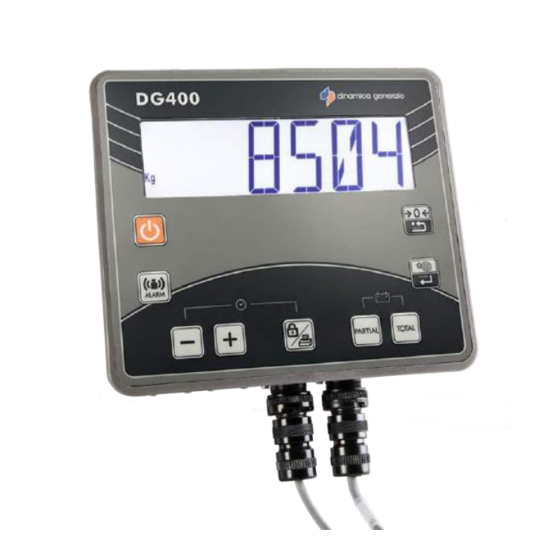
General Information INDICATOR DG400 RevB0 CONFIGURATION ON /OFF key. Connectors. Function and setting key. 6 digit LCD display 45 mm to show the weight. Fixing support. Identification label. -
Page 7: Keyboard
General Information INDICATOR DG400 RevB0 KEYBOARD ON – OFF Press this key in order to switching on / off the indicator From the TOTAL WEIGHT mode, press this key in order to set the ALARM weight. When this value has been reached, the alarm will start 1- Both in PARTIAL/TOTAL and in NET/GROSS it is possible to suspend the weighing by pushing this key. -
Page 8: Connections Scheme
General Information INDICATOR DG400 RevB0 CONNECTIONS SCHEME Power and sensor connections (system with junction box) -
Page 9: Power And Sensor Connection (System Without Junction Box)
General Information INDICATOR DG400 RevB0 Power and sensor connection (system without junction box) -
Page 10: Accessories Connection (System With Junction Box)
General Information INDICATOR DG400 RevB0 Accessories connection (system with junction box) -
Page 11: Accessories Connection (System Without Junction Box)
General Information INDICATOR DG400 RevB0 Accessories connection (system without junction box) -
Page 12: Setting Of The Parameters
Configuration INDICATOR DG400 RevB0 SETTING OF THE PARAMETERS ACCESS TO THE PASSWORD MENU Switch on by pressing Once the software revision has come up, the message “------“ will appear on the display. Press the setting key to enter in password configuration. The message “Config.”... -
Page 13: To Exit The Password Menu
Configuration INDICATOR DG400 RevB0 * NOTE 1 To return to the -PS- PASSWORD mode, switch off the indicator and go back to point 1. TO EXIT THE PASSWORD MENU Set the password ZERO by using the MINUS and PLUS keys. -
Page 14: List Of The Passwords
Configuration INDICATOR DG400 RevB0 The message “-----” will appear on the indicator. Afterwards the message TOTAL, which indicates the TOTAL WEIGHT mode, will be displayed ; therefore the weight value is visualized on the display. LIST OF THE PASSWORDS Calibration... - Page 15 Configuration INDICATOR DG400 RevB0 Press MINUS and PLUS to change the value of this parameter if necessary. The calibration value depends on the load cells’ number and capacity. Please contact dinamica generale® for further details. If the full equipment has been bought, the indicators have already been gauged by DG.
-
Page 16: Password 19: How To Set The Base Parameters
Configuration INDICATOR DG400 RevB0 PASSWORD 19: HOW TO SET THE BASE PARAMETERS Password 19 includes the following base parameters: From the PASSWORD mode set up the number 19, by using the MINUS and PLUS keys. Press the ENTER key or press at the same time PARTIAL and TOTAL keys. -
Page 17: Password 19: Setting Procedure
Configuration INDICATOR DG400 RevB0 PASSWORD 19: SETTING PROCEDURE ADDRESS (Range: 1-255; Default: 3) ADDRESS is an identification code which allows the indicator to be connected by RF only with those devices that use the same address to communicate, without interference with other devices using different addresses. - Page 18 Configuration INDICATOR DG400 RevB0 RESOLUTION OF THE WEIGHT VISUALIZATION (Default:5) Displayed weight resolution setting. The setting up of the division of the Kg. to be displayed can be set at 1, 2, 5, 10, 20 or 50 kg always by pressing the PLUS and MINUS keys.
- Page 19 Configuration INDICATOR DG400 RevB0 To confirm and go on to the next parameter, press the ENTER key or press at the same time the PARTIAL and TOTAL keys. ALARM TIME (Range: 0-60; Default:7) The programming of the sound alarm time at the end of the load/unload phase.
- Page 20 Configuration INDICATOR DG400 RevB0 LANGUAGE: SELECTION OF THE LANGUAGE Selection of the language for the printer The selection of the language is made using the PLUS and MINUS button. English Czech Italian Croatian Spanish Slovak German Slovenian French Swedish Portuguese...
- Page 21 Configuration INDICATOR DG400 RevB0 To confirm and go on to the next parameter, press the ENTER key or press at the same time the PARTIAL and TOTAL keys. DT ENABLED: DATA TRANSFER (Default: 0) Setting of the Data Transfer: 0 = NO...
-
Page 22: Password 45: How To Set The Calibration With A Reference Weight
Configuration INDICATOR DG400 RevB0 PASSWORD 45: HOW TO SET THE CALIBRATION WITH A REFERENCE WEIGHT From the modality “PASSWORD 0“, select number 45 with the PLUS and MINUS keys. Confirm by pressing the ENTER key or by pressing at the same time PARTIAL and TOTAL key. - Page 23 Configuration INDICATOR DG400 RevB0 If the message “-----” appears, it means that the ZERO value will be saved. The message “--STEP2-” and after the message “SET VALUE” will appear for 2 seconds, it means that the second step of calibration is starting.
- Page 24 Configuration INDICATOR DG400 RevB0 The calibration value will be shown on the display; in this situation load on the mixer the reference weight and insert on the display the value (in Kgs or Lbs) of the reference weight, then confirm with the ENTER key or with the PARTIAL and TOTAL keys.
- Page 25 Configuration INDICATOR DG400 RevB0 The indicator return to password PASSWORD 46: INVERSE CALIBRATION WITH SAMPLE WEIGHT This procedure allows to carry out the calibration of the weighing system on the basis of a known weight that must be appropriately weighed on the medium in which the weighing system is mounted.
- Page 26 Configuration INDICATOR DG400 RevB0 Load the weight on the mixer and insert the value of the reference weight placed in the mixer (in Kg or Pounds) with PLUS and MINUS keys, then confirm with key. The value is only indicative The message “------”...
-
Page 27: Password 67: How To Modify The Weighing
Configuration INDICATOR DG400 RevB0 The message “----“ will appear, the Zero value will be saved. If the message “Calib Ok!” will appear, it means that the calibration procedure has finished successfully. After the end of the procedure the indicator returns to Set password -/+. - Page 28 Configuration INDICATOR DG400 RevB0 By pressing the MINUS and PLUS keys, set up the percentage of weighing modification. Selectable range: from – 10,0% to + 10,0%. Minimum range 0,1%. To confirm the parameter press the ENTER key or the PARTIAL and TOTAL keys.
-
Page 29: Password 99: How To Set The Weight Limit
Configuration INDICATOR DG400 RevB0 The indicator return to password 0. PASSWORD 99: HOW TO SET THE WEIGHT LIMIT (Range: 100-99999; Default:15000) From the -PS- PASSWORD mode set up the number 99, with the MINUS and PLUS keys. Press the ENTER key or press at the same time PARTIAL and TOTAL key. - Page 30 Configuration INDICATOR DG400 RevB0 To confirm the parameter press the ENTER key or press the PARTIAL and TOTAL keys. The message -SAVED- is displayed. The indicator return to password 0.
-
Page 31: Password 444: How To Set The Working Mode
Configuration INDICATOR DG400 RevB0 PASSWORD 444: HOW TO SET THE WORKING MODE (Default: IP-t Partial/Total) From the PASSWORD mode set up the number 444, by using the MINUS and PLUS keys. Confirm by pressing the ENTER key or by pressing at the same time... - Page 32 Configuration INDICATOR DG400 RevB0 In this configuration it is not possible to store one tare in order to see it again, since the system’s tare and zero coincide. This function is recommended especially in the case of feed mixers or trailers in general.
-
Page 33: Password 454: How To Set The Unit Of Measurement
Configuration INDICATOR DG400 RevB0 OPERATION DISPLAY NET WEIGHT GROSS WEIGHT TARE Press PARTIAL Press TOTAL Load 100KG Press TOTAL Load 500KG Press TOTAL Unload all Press TOTAL To confirm the parameter press the ENTER key or the PARTIAL and TOTAL keys. - Page 34 Configuration INDICATOR DG400 RevB0 Set up the unit of measurement in kilograms (kg) (0–KILOGRAMS) or in pounds (lb) (I–POUNDS) by pressing the MINUS and PLUS keys. The same choice will be indicated beside the weight value on all the printed coupons.
-
Page 35: Use Of The Microcomputer
INDICATOR DG400 RevB0 USE OF THE MICROCOMPUTER SWITCH ON a) Switch on the indicator by pressing , the name DG 400 and the last software revision appears on the display, then the message “------”. b) A weight value appears on the display. -
Page 36: Net/Gross Working Mode
INDICATOR DG400 RevB0 The zeroing of the system is a very delicate passage. It depends also on the machine’s conditions, on the soil’s and temperature’s conditions, and on the mechanical stresses. In fact, if the machine is moving on a sloping surface or it is subjected to a different range of temperature or to different mechanical conditions, it is likely that the value displayed may change during the weighing process. - Page 37 INDICATOR DG400 RevB0 NET/GROSS WEIGHT a) In this mode the PARTIAL key is used to store a tare. By holding the key for 3 seconds, the messages “SAVED and “GROSS” appears. Now the weight “0” is displayed and previously displayed summed up to the gross weight.
- Page 38 INDICATOR DG400 RevB0 c) Confirm the set weight by pressing the PARTIAL key and go on with the load/upload phase. The weight is displayed with a decreasing order, despite the fact it is loading/unloading. Once the percentage that has been set...
- Page 39 INDICATOR DG400 RevB0 ADDICTIONAL FUNCTIONS BATTERY CONTROL Hold pressed the PARTIAL and TOTAL keys at the same time in TOTAL WEIGHT or GROSS WEIGHT mode, in order to display the voltage of the battery. HOURS and MINUTES: 1. DISPLAY Keeping pressed at the same time BLOCK PRINT and MINUS keys, hour and minutes will be shown on the display.
- Page 40 INDICATOR DG400 RevB0 THE NEXT FUNCTIONS ARE AVAILABLE ONLY IF THE INSTRUMENT IS EQUIPPED TO BE CONNECTED TO THE PRINTER (FULL VERSION). PRINT a) In order to print the weight value, hold pressed the PRINT BLOCK key for 3 seconds, confirmed message on the display “PRESS 3 TO...
-
Page 41: Legend
INDICATOR DG400 RevB0 LEGEND CONVENTIONAL SIGNS This user’s manual uses some conventional signs, in order to lead the user during the reading of important instructions and advices; these regard especially the setting of the parameters of the system and thus its correct working. -
Page 42: Optional Accessories
In order to advance of the paper by hand, press the Feed key on the printer panel. WiNET™ MODEM Compatible modem with all dinamica generale accessories and indicators, that is able to manage a wireless network between several devices without any interference issues. -
Page 43: Weight Repeater
Red, Green and Yellow "diodes LED" display. IP65 protection. Display view: over 50 m (165 feet). Simple and direct connection to all microcomputers dinamica generale with the WiNET interface. Metal watertight case protected against radio frequency noises. -
Page 44: Easy Control 2
Remote control in order to command the indicator all the way up to 25 meters (82 feet). With the WiNET Modem interface, the remote control can be used with all dinamica generale wireless accessories without any interference: all devices talk together in the same network. -
Page 45: Searching For Faults
Service INDICATOR DG400 RevB0 SEARCHING FOR FAULTS MOTION ALARM DISPLAY CAUSE SOLUTION Solution1: Cause1 do the TARE. The signal coming from the sensors shows sudden and important weight DG400 change. Solution2: do the calibration with password 12 Cause2 and then do the TARE A connection cable or a load cell does not work correctly. - Page 46 Service INDICATOR DG400 RevB0 OVERRANGE ALARM DISPLAY CAUSE SOLUTION Cause1 Solution1: The microcomputer can not read the do the TARE. signal of the load cells: the load cell connection cable does not work correctly. DG400 Solution2: Cause2 do the calibration with password 12 A connection cable or a load cell does and then do the TARE.
-
Page 47: Check The Damaged Components
Service INDICATOR DG400 RevB0 CHECK THE DAMAGED COMPONENTS DEFINE THE TEST PROCEDURE: HAVE YOU GOT A WEIGHING SIMULATOR DG 979-0007? HAVE YOU GOT A SYSTEM WITH JUNCTION BOX? EXECUTE EXECUTE PROCEDURE 4 PROCEDURE 3 EXECUTE HAVE YOU GOT A PROCEDURE 2... - Page 48 Service INDICATOR DG400 RevB0 PROCEDURE 1 Ref. YES / YES Check the working of the scale a) Switch off the microcomputer. b) Disconnect the sensor cable between the scale and the junction box. c) Connect the WEIGHT SIMULATOR (calibrator 979-0007) with the lever in position “Var” (varying) to the SENSORS connector of the scale.
- Page 49 Service INDICATOR DG400 RevB0 RESULT CAUSE ACTION Zero stable and correct The sensor cable and the functioning Proceed with the other tests junction box are NOT damaged Try to dry the junction box and Functioning not correct only in repeat the test; in case you do The junction is damaged or wet some junction box connectors.
- Page 50 Service INDICATOR DG400 RevB0 PROCEDURE 2 Ref. YES / NO Check the functioning of the scale a) Switch off the microcomputer. b) Disconnect all the sensors. c) Connect the WEIGHT SIMULATOR (calibrator) with the lever in " “Var” (varying) position to one of the sensor connectors of the weighing system.
- Page 51 Service INDICATOR DG400 RevB0 PROCEDURE 3 Ref. NO / YES Check the functioning of the SYSTEM and of the SENSORS a) Switch off the microcomputer. b) Open the JUNCTION BOX. c) Just leave connected one sensor and the cable to the scale (SENSORS’ CABLE).
- Page 52 Service INDICATOR DG400 RevB0 PROCEDURE 4 Ref. NO / NO Check the functioning of the SYSTEM and of the SENSORS a) Switch off the microcomputer. b) Just leave connected one sensor to the scale. c) Switch on the microcomputer. d) Do the TARE (use the microcomputer’s manuals for instructions).
-
Page 53: Dichiarazione Di Conformita' - Declaration Of Conformity Konformitätserklärung - Déclaration De
Il sottoscritto, designato a legale rappresentante della Dinamica Generale s.p.a. , via Mondadori 15, Poggio Rusco (MN) - Italy, dichiara che i prodotti sottoelencati: EN The undersigned, an authorised officer of Dinamica Generale s.p.a. , via Mondadori 15, Poggio Rusco (MN) - Italy, hereby declares that the products listed hereunder: Der Unterzeichner, rechtlicher Vertreter der Dinamica Generale s.p.a. -
Page 54: Warning
Rules INDICATOR DG400 RevB0 WARNING The power supply must be connected directly to the battery or to a regulated feeder. If it is not the case, DG is not responsible for damages to the micro computer. Disconnect the power supply cable from the micro computer when the battery is undergoing recharge. -
Page 55: Environment: Disposal Rules
Rules INDICATOR DG400 RevB0 ENVIRONMENT: Disposal Rules This marking on the product or on its packaging means that this product can not be disposed with normal household waste. You are responsible for disposal of this equipement in a correct way and in according to local regulations. -
Page 56: Guarantee
NOTES: dinamica generale® has the faculty to modify the content of this handbook due to hardware and software implementations in order to improve their products and thus to guarantee the best service to their users. - Page 57 This users manual intends to take you through the different performances of the weighing system in the easiest way and to show you some new functions as well. dinamica generale® did not forget to provide you even with the basic information: the configuration, the use of different accessories at your disposal, the service of “searching for...
- Page 58 ISO 14001:2004 ISO 13485:2012...
- Page 59 Cod. 985-0092 Rev. B0...
Need help?
Do you have a question about the DG400 and is the answer not in the manual?
Questions and answers
I Need the color codes to connect the load cells to the junction box
не нужны цветовые обозначения от распедкоробки тезодачиков до контроллера