
Subscribe to Our Youtube Channel
Summary of Contents for Muller Elektronik SPRAYDOS
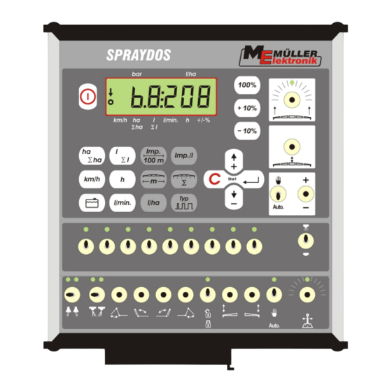
- Page 1 Installation and operating instructions SPRAYDOS Version: V2.20160707 30221021-02-EN Read and follow these operating instructions. Keep these operating instructions in a safe place for later reference.
- Page 2 Company details Document: Installation and operating instructions Product: SPRAYDOS Document number: 30221021-02-EN As of software version: 15.10.13 Original language: German Müller-Elektronik GmbH & Co.KG Franz-Kleine-Straße 18 33154 Salzkotten Germany Phone: ++49 (0) 5258 / 9834 - 0 Fax: ++49 (0) 5258 / 9834 - 90 Email: info@mueller-elektronik.de...
-
Page 3: Table Of Contents
............................ 19 6.2.6.1 Manifold type ............................. 19 6.2.6.2 Control constants ............................20 6.2.7 "+ 10 %" , "- 10 %" ,"100 %" keys ..............21 Copyright Müller-Elektronik GmbH & Co.KG, Installation and operating instructions SPRAYDOS (07.2016) Page - 3 -... - Page 4 APPENDIX ..............................29 Technical data ............................29 8.1.1 Long SPRAYDOS version ......................... 29 8.1.2 Short SPRAYDOS version ........................29 LIST OF DIAGRAMS ..........................30 Page - 4 - Copyright Müller-Elektronik GmbH & Co. KG, Installation and operating instructions SPRAYDOS (07.2016)
-
Page 5: Introduction
The SPRAYDOS board computer is a new development on the basis of the well tried and tested SPRAY-Control board computer. The SPRAYDOS has up to 9 boom section switches with a main switch, the manual or automatic regulation of the spray rate and up to 4 hydraulic functions (the long version allows a further 10 hydraulic functions as soon as foam marker and corner nozzles). -
Page 6: Safety Instructions
Before welding on the tractor or on an attached machine, interrupt the power supply to the SPRAYDOS. Only use a soft damp cloth with clear water or a little glass cleaning agent to clean the SPRAYDOS. Operate the keys with your finger tips but avoid using fingernails. -
Page 7: Safety Notice For The Subsequent Installation Of Electrical And Electronic Devices And /Or Components
An antenna should only be installed professionally ensuring that there is a good earth connection between the antenna and the vehicle chassis. Please refer to the manufacturer's installation instructions for cabling and installation as well as the maximum current consumption. Copyright Müller-Elektronik GmbH & Co.KG, Installation and operating instructions SPRAYDOS (07.2016) Page - 7 -... -
Page 8: Ec Declaration Of Conformity
EMV Directive 2004/1008/EG: Dieses Produkt ist in Übereinstimmung mit folgenden nationalen und harmonisierten Normen im Sinne der EMV-Richtlinie 2004/108/EG hergestellt: EN ISO 14982 Page - 8 - Copyright Müller-Elektronik GmbH & Co. KG, Installation and operating instructions SPRAYDOS (07.2016) -
Page 9: Overview And System Description
DIN 9680 brown blue Tractor Implement Machine signal distributor for sprayer Sensor X (Wheel) Hydraulic signal distributor – long SPRAYDOS version Diagram 4-1 SPRAYDOS overview Copyright Müller-Elektronik GmbH & Co.KG, Installation and operating instructions SPRAYDOS (07.2016) Page - 9 -... - Page 10 Bracket S for mounting the cap profile rail Basic console, to be mounted on the tractor cabin. For fitting the bracket with cap profile rail and battery connection. Battery connecting cable for the SPRAYDOS voltage supply, connection to a 12-volt battery. Machine signal distributor Combines the sensor and actuator connections on the machine.
-
Page 11: System Description
A wheel/cardan speed sensor [9] can be connected directly to SPRAYDOS in order to determine the speed. The SPRAYDOS can be connected directly to the signal socket [10] on the tractor using a connecting cable. By means of a switch integrated in the connecting cable it is possible to switch between wheel/cardan and a radar device. -
Page 12: Installation Instructions
The distance to the radio or to the radio antenna should be at least 1 m. Attach the bracket [4] to the tube of the basic console. Mount the cap profile rail [2] on to the bracket. Push the SPRAYDOS computer [1] from above on to the profile and secure using the wing nuts [3]. - Page 13 = + 12 volts blue = ground CAUTION The negative pole on the battery must be connected to the tractor's chassis. Copyright Müller-Elektronik GmbH & Co.KG, Installation and operating instructions SPRAYDOS (07.2016) Page - 13 -...
-
Page 14: Sensor X (Calculation Of The Distance)
If an X sensor is connected in the machine distributor, no sensor is to be connected to the SPRAYDOS. Adapter cable for tractors with signal socket In this case it is not necessary to install the X sensor. The SPRAYDOS is connected to the tractor's signal socket using the adapter cable [10]. Page - 14 - Copyright Müller-Elektronik GmbH &... -
Page 15: Connection On The Field Sprayer
Connection on the field sprayer The attached or trailed field sprayer is connected via a 39 channel machine plug manifold. With the SPRAYDOS long version the machine plug – hydraulic must be connected in addition. Copyright Müller-Elektronik GmbH & Co.KG, Installation and operating instructions SPRAYDOS (07.2016) -
Page 16: Operating Instructions
Before the device can put into operation, the machine-specific data must be entered: 6.2.1 "Working width" key This key is used to enter the working width Page - 16 - Copyright Müller-Elektronik GmbH & Co. KG, Installation and operating instructions SPRAYDOS (07.2016) -
Page 17: Impulses/100M" Key
The required spray rate is communicated to the computer using this key. If the switch is in automatic position electronics control the pressure and subsequently the spray rate automatically. Copyright Müller-Elektronik GmbH & Co.KG, Installation and operating instructions SPRAYDOS (07.2016) Page - 17 -... -
Page 18: Impulses / Litre" Key
With the nozzle method the quantity sprayed is measured at a nozzle and projected to the total number of nozzles. The procedure is as follows: Fill the tank with water. > Secure a measuring jug below a nozzle. > Page - 18 - Copyright Müller-Elektronik GmbH & Co. KG, Installation and operating instructions SPRAYDOS (07.2016) -
Page 19: Type" Key
Manifold without balanced pressure function. 2.15 Balanced pressure manifold with reflux measurement 3.15 Spraying devices without balanced pressure function Manifold type (number before the comma) Copyright Müller-Elektronik GmbH & Co.KG, Installation and operating instructions SPRAYDOS (07.2016) Page - 19 -... -
Page 20: Control Constants
Regulation can be seen in the display l/ha. Control constants can be within the range of 1 to 99. See also 6.2.6.1 "Manifold types". Page - 20 - Copyright Müller-Elektronik GmbH & Co. KG, Installation and operating instructions SPRAYDOS (07.2016) -
Page 21: Keys
This key has a dual function. When the key is pressed for the first time, the quantity spray since activating the start function (6.3.1 ) is displayed for 10 seconds. In addition an arrow appears at the bottom of the display above . If, within Copyright Müller-Elektronik GmbH & Co.KG, Installation and operating instructions SPRAYDOS (07.2016) Page - 21 -... -
Page 22: Speed" Key
Spraying pressure +/- key This key is for manual adjustment of the spraying pressure in manual operation mode. Manual operation is selected by means of the switch. Page - 22 - Copyright Müller-Elektronik GmbH & Co. KG, Installation and operating instructions SPRAYDOS (07.2016) -
Page 23: Boom Section Switch
Configuring the section switches If you connect a Spraydos with nine section switches to a sprayer with five sections, you can set that only every second switch is used. In doing so, please note that the LEDs above unused switches are also illuminated as soon as they are switched up. -
Page 24: Calibrating Hydraulic Functions
Is switched off in calibration mode, and flashes to indicate completion. The same LED is used for all of the calibrations. Page - 24 - Copyright Müller-Elektronik GmbH & Co. KG, Installation and operating instructions SPRAYDOS (07.2016) -
Page 25: Activating Calibration Mode
You have taught the computer where the right side is. - Move the boom into a horizontal position. > The boom is horizontal. Copyright Müller-Elektronik GmbH & Co.KG, Installation and operating instructions SPRAYDOS (07.2016) Page - 25 -... -
Page 26: Calibrating The Drawbar Steering
The drawbar was moved a little to the right. Lift the magnet briefly and apply it again. > The LED flashes briefly. Page - 26 - Copyright Müller-Elektronik GmbH & Co. KG, Installation and operating instructions SPRAYDOS (07.2016) - Page 27 You have calibrated the maximum left position. The calibration is complete. Lift the magnet. > LED is off. Calibration mode is terminated. Copyright Müller-Elektronik GmbH & Co.KG, Installation and operating instructions SPRAYDOS (07.2016) Page - 27 -...
-
Page 28: Maintenance
Rinse the flow meter with water each time after use. At the end of the season check the run of the impeller wheel and replace if necessary. At the beginning of each season carry out a calibration process (see 6.2.5). Page - 28 - Copyright Müller-Elektronik GmbH & Co. KG, Installation and operating instructions SPRAYDOS (07.2016) -
Page 29: Appendix
2.50A / 1.53A 2.50A / 1.93A Hydraulic cpl. (opt.) 4.00A / 2.44A 4.00A / 3.08A Slope Regulation - duration 4.00A / 2.44A 4.00A / 2.44A Copyright Müller-Elektronik GmbH & Co.KG, Installation and operating instructions SPRAYDOS (07.2016) Page - 29 -... -
Page 30: List Of Diagrams
List of diagrams Diagram 4-1 SPRAYDOS overview ............................ 9 Diagram 5-1 Sensor X at the cardan shaft ........................14 Diagram 5-2 Sensor X on the tractor's wheel ........................14 Diagram 6-1 Display ................................16 Diagram 6-2 Section switches ............................23 Diagram 6-3 Operating elements that are required for calibration ..................
Need help?
Do you have a question about the SPRAYDOS and is the answer not in the manual?
Questions and answers