
Related Manuals for ANK DAC 2.1 Signature

Summary of Contents for ANK DAC 2.1 Signature
- Page 1 DAC 2.1 Signature Construction Manual Version 6.11, June 2019 audionotekits@rogers.com 1-613-822-7188...
-
Page 2: Table Of Contents
…………………………………………..…….…… Mains Transformer Preparation ……………………..……………………………………….…… 2.6.1 Attaching the Ground Lug …………………………………………………………………… Configuring the Mains Primary Winding …........………………………… Initial Mains Secondary Wiring ………………………………………………………………………………… Installing the Mains Transformer and AC Connections ………………………………………… Copyright © 2019 ANK Audio Kits www.AudioNoteKits.com audionotekits@rogers.com Page 2... - Page 3 Section 5 — Digital Power Supply Board ……………………………………………………….……………… Overview ………………………………………………………………………………………..…………..…….…… Parts List ………………………………………………………………………………………..…………..…….…… Construction ………………………………………………………………………………….….……………..…….…… Installing the LEDs ………………………………………………………………………...………..……..….…… Installing the Capacitors ……………………………………………………………………..……………… Installing the Schottky Diodes ………………………………………………………..…………………………… Installing the Resistors …………………………………………………………..…………………………..…….…… Installation and Wiring ………………………………………………………………..……………………..…….…… Copyright © 2019 ANK Audio Kits www.AudioNoteKits.com audionotekits@rogers.com Page 3...
- Page 4 Connecting the XLR Input …………………………………………………………………………. 112 Section 12 — Wiring the Output Connections ………………..…………………………..……………… 12.1 Wiring the Output Connections ………………………………………………………………………………………. 113 Section 13 — Turn-on Procedure ……………………………………………………………………….. 13.1 Turn-on ............................13.2 Debugging ............................Copyright © 2019 ANK Audio Kits www.AudioNoteKits.com audionotekits@rogers.com Page 4...
- Page 5 15.4 Tube Rolling ……………………..………………………….……………………………………………….…...………… 15.4.1 6922 ……………………..…………………..……….………………………..……………………...…………… 15.4.2 6X5 and ECL82 ……………………..………………………………………………………….…….…………… 15.5 Thanks ……………………..…………………………………………………..……………….…………….………………….… Appendix ……………………………………………..……………………………………………………..….……….……….…… 121 World Mains Voltages Wiring Diagrams …………………………………………….…..…….…… Resistor Color Code Reference ……………………………………………………………………….…..…….…… 128 Copyright © 2019 ANK Audio Kits www.AudioNoteKits.com audionotekits@rogers.com Page 5...
-
Page 6: Section 1 - Introduction
Section 1 Introduction Thanks for purchasing the ANK Audio Kits DAC 2.1 Signature. Our goal is to provide you with the highest quality kit that you will build from scratch with these instructions. This is very high end and sophisticated piece of audio equipment that will surely become a showpiece of your sound system. -
Page 7: About Ank Audio Kits
ANK Audio Kits began offering this service for Level 4 and 5 products so that a significant investment in a kit could be turned into a work of art! Since ANK Audio Kits was born in 2004, over 2,500 kits have been shipped to customers worldwide. Clearly, there is a real demand for high end audio kits and ANK Audio Kits has been delivering the goods now for 15 years. -
Page 8: Basic Operation Of The Dac
1.2.1 Overview The ANK Audio Kits DAC 2.1 is one of our longest running products with a significant following. Originally developed as the DAC 2.1A and DAC 2.1B variants, we now have concentrated production on the upgraded variant that is now known as simply the DAC 2.1 Signature. The DAC 2.1 Signature offers velvet smooth operation with no digital artifacts or treble edge. - Page 9 Further, the DAC 2.1 Signature's I/V transformers couple and maximize energy transfer during the current-to-voltage phase of the conversion from the digital converter to the analog section, resulting in increased dynamics. These transformers were specially designed by Audio Note (UK) engineering.
-
Page 10: Component Placement
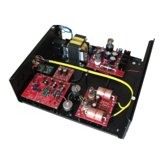
1.2.2 Component Placement Here’s a completed DAC 2.1 Signature Copyright © 2019 ANK Audio Kits www.AudioNoteKits.com audionotekits@rogers.com Page 10... -
Page 11: Block Diagram
1.2.3 Block Diagram The graphic below shows the block diagram overview of how the DAC works: Copyright © 2019 ANK Audio Kits www.AudioNoteKits.com audionotekits@rogers.com Page 11... -
Page 12: Equipment
YouTube videos for soldering lessons and examples.) The solder should flow freely; if it’s forming balls then there is likely a problem with the tip, the temperature, or (sometimes) the surface. Feel free to contact us for help! For example, WBT-0800. Copyright © 2019 ANK Audio Kits www.AudioNoteKits.com audionotekits@rogers.com Page 12... -
Page 13: Components
That way of looking at things sometimes now no longer applies. Please be assured that all resistors supplied with ANK Audio Kits are rated at least per the specified wattage: in some cases, a higher than specified wattage may be supplied. -
Page 14: Diodes
This makes for easy soldering to a PCB, an RCA connector, or a transformer terminal. So it's a good idea to practice this a little before starting the kit. Copyright © 2019 ANK Audio Kits www.AudioNoteKits.com audionotekits@rogers.com... -
Page 15: Wire Color
1.4.10 Optional Finishing Touches From time to time we get asked about some of the build details of the ANK Finished Products that you can see in the pictures in the "Assembled Kits Gallery!" (https://ankits.smugmug.com/) on our website. -
Page 16: Organization Of This Manual
9. Interwiring the Digital DAC Board 10. Installing the I/V Transformers 11. Installing the Rear Faceplate and Connectors 12. Wiring the Output Connections 13. Turn-on Procedure 14. Finishing Touches 15. Final Thoughts Appendix Copyright © 2019 ANK Audio Kits www.AudioNoteKits.com audionotekits@rogers.com Page 16... - Page 17 Here's another way of looking at how the manual is organized and how the sections fit into the 'big picture': the main sections are mapped so that they mirror how the components will be positioned in the DAC chassis: Copyright © 2019 ANK Audio Kits www.AudioNoteKits.com audionotekits@rogers.com...
-
Page 18: Electrical Safety Warning
There are sufficient voltages in this kit to give you a very nasty and harmful shock, so be careful when powering on, debugging, and probing around. Please contact ANK Audio Kits via phone or email (audionotekits@rogers.com) to discuss any precautions necessary when building the kit if you feel unsure about what you are doing at any stage of the build. -
Page 19: Section 2 - Mechanical Assembly And Initial Mains Transformer Wiring
When you receive the kit you will have a series of kit bags. In the following sections we'll be using the: Hardware bag (made up of individual bags for each section of the kit) IEC bag (containing the Rocker Switch, IEC and premade cables, fuses, etc.) Copyright © 2019 ANK Audio Kits www.AudioNoteKits.com audionotekits@rogers.com Page 19... -
Page 20: Installing The Feet
Install each foot in the hole in the chassis closest to the corner and secure it with an M4 nut on the inside of the chassis. Don't overtighten the screw; you could damage the foot. Copyright © 2019 ANK Audio Kits www.AudioNoteKits.com audionotekits@rogers.com... - Page 21 When completed your feet will look like the picture below. You're on your way! Copyright © 2019 ANK Audio Kits www.AudioNoteKits.com audionotekits@rogers.com Page 21...
-
Page 22: Installing The Choke
Neatly lay out the necessary hardware close at hand: 4 M4 screws 4 M4 washers 4 M4 Keps K-Lock Nuts (these are M4 nuts with attached locking washers) Copyright © 2019 ANK Audio Kits www.AudioNoteKits.com audionotekits@rogers.com Page 22... - Page 23 M4 screws and washers from above into the four holes on the base of the Choke, so that you can then insert the whole unit into the chassis. Copyright © 2019 ANK Audio Kits www.AudioNoteKits.com audionotekits@rogers.com...
- Page 24 Finish up by tightening things up from below with a pair of pliers. Copyright © 2019 ANK Audio Kits www.AudioNoteKits.com audionotekits@rogers.com...
- Page 25 When installed, the Choke should be positioned as shown below: Time for a break! Copyright © 2019 ANK Audio Kits www.AudioNoteKits.com audionotekits@rogers.com Page 25...
-
Page 26: Installing The Chassis Ground
Install an M4 16mm PAN head screw, washer, and nut into position in the unpainted area on the chassis near the Choke, as shown below. This will act as the chassis ground. Copyright © 2019 ANK Audio Kits www.AudioNoteKits.com audionotekits@rogers.com... -
Page 27: Installing The Iec Socket And Rocker Switch
Install the self-locking rocker switch by pressing it in from the back of the chassis; it will snap into position. The correct orientation of the IEC and Rocker Switch Copyright © 2019 ANK Audio Kits www.AudioNoteKits.com audionotekits@rogers.com Page 27... -
Page 28: Mains Transformer Preparation
DAC. It's important to understand what these connections are and where they're located. We recommend that you hold the transformer while looking at the three diagrams below to familiarize yourself with 'what goes where'. Copyright © 2019 ANK Audio Kits www.AudioNoteKits.com audionotekits@rogers.com... -
Page 29: Attaching The Ground Lug
Trim the Green wire to 7", strip 1/2" from the end, tin it, and insert it into the Ground lug provided in the kit bag. Copyright © 2019 ANK Audio Kits www.AudioNoteKits.com audionotekits@rogers.com... -
Page 30: Configuring The Mains Primary Winding
DC filaments for the 6922 tubes 9-0-9 shielded and used for the Digital Power Supply 0-6.3 used for the AC filament voltage for the tubes on the M2 Power Supply board Copyright © 2019 ANK Audio Kits www.AudioNoteKits.com audionotekits@rogers.com Page 30... - Page 31 We're now going to set up the Mains for 120V operation by wiring the two windings in parallel. The first step is to add a wire from the 0 of one winding to the 0 of the other winding. Copyright © 2019 ANK Audio Kits www.AudioNoteKits.com audionotekits@rogers.com...
- Page 32 Tin the 0 lead at the top of the Primary and then position the wire on the lead and add heat — the tinned effect of the two surfaces will melt them together. Copyright © 2019 ANK Audio Kits www.AudioNoteKits.com audionotekits@rogers.com...
- Page 33 120 tag. To recap: the Black wire is connected to the top 0 connection and the Red wire is connected to the bottom 120 connection. Copyright © 2019 ANK Audio Kits www.AudioNoteKits.com audionotekits@rogers.com Page 33...
-
Page 34: Initial Mains Secondary Wiring
(300–0): at the same time add a 12” piece of Black wire to the second tap (300) as shown. Later we'll solder this wire to the M2 Power Supply board. Copyright © 2019 ANK Audio Kits www.AudioNoteKits.com audionotekits@rogers.com... -
Page 35: Installing The Mains Transformer And Ac Connections
With the wiring above now completed we can now position the Mains transformer into the but do not secure it as we have more work to do around the IEC section chassis... Copyright © 2019 ANK Audio Kits www.AudioNoteKits.com audionotekits@rogers.com... - Page 36 In this section, refer to the diagram below for the AC Power On/Off and Ground Connections for 120V. Copyright © 2019 ANK Audio Kits www.AudioNoteKits.com audionotekits@rogers.com Page 36...
- Page 37 Take the prepared Black and Red wires with the 4 crimps on the ends (2 on each end). Carefully examine the IEC graphic on the previous page, then attach the prepared Black and Red wires to the IEC socket as shown. Copyright © 2019 ANK Audio Kits www.AudioNoteKits.com audionotekits@rogers.com...
- Page 38 Here's a picture of the completed rocker switch and IEC wiring: check it carefully Now that we've completed this wiring, . Go back and go over each step again. Take your time. Copyright © 2019 ANK Audio Kits www.AudioNoteKits.com audionotekits@rogers.com Page 38...
- Page 39 M4 screws, nuts, and serrated washers. Position the serrated washers closest to the M4 nut, on the underside of the chassis. Here's a view underneath the chassis, showing the screws in position… Copyright © 2019 ANK Audio Kits www.AudioNoteKits.com audionotekits@rogers.com...
- Page 40 …and here's a view from the top: Congratulations on the Choke and Mains installation! Now we'll move onto the M2 Power Supply board. But first, Time for another break. Copyright © 2019 ANK Audio Kits www.AudioNoteKits.com audionotekits@rogers.com Page 40...
-
Page 41: Section 3 - M2 Power Supply Board
If there are any problems, we'll try and diagnose what's wrong. If that doesn't help, please contact us by phone or email (audionotekits@rogers.com) and we will help you resolve the issue. Copyright © 2019 ANK Audio Kits www.AudioNoteKits.com audionotekits@rogers.com... - Page 42 Install the Resistors Install the 6V2 Wires Install the Capacitors Install the Bridge Rectifier Install the Zener Diode The Filament Section Additional Wiring Copyright © 2019 ANK Audio Kits www.AudioNoteKits.com audionotekits@rogers.com Page 42...
-
Page 43: Installing The Valve Bases
Schematics may change from time to time, but we've included this schematic as a guide. If you find any differences between this schematic and your board and parts — and it concerns you, just give us a call. Copyright © 2019 ANK Audio Kits www.AudioNoteKits.com audionotekits@rogers.com... - Page 44 Once completed, you can insert the 9-pin valve base at V1; it only goes one way. Again, use some masking tape to secure it so that it's level and then solder it into position. Well done! Copyright © 2019 ANK Audio Kits www.AudioNoteKits.com audionotekits@rogers.com...
-
Page 45: Installing The Resistors
Appendix A.1. It's a good idea to orient your resistors so that the color codes can be read from left to right; it makes it easier to spot any issues. Copyright © 2019 ANK Audio Kits www.AudioNoteKits.com audionotekits@rogers.com... - Page 46 Hold the lead that you are about to clip with one hand so that it does not go flying off and hit you in the face or eye! Another great tip: Orient your resistors so that the color codes can be more easily read from left to right with consistency. Copyright © 2019 ANK Audio Kits www.AudioNoteKits.com audionotekits@rogers.com...
- Page 47 Resistors in Place Copyright © 2019 ANK Audio Kits www.AudioNoteKits.com audionotekits@rogers.com Page 47...
-
Page 48: Installing The 6V2 Wires
We've provided you with a long length of about 80 cm or almost a complete meter. Have a good look at the pictures below; these show the top and bottom of the board and the wiring that we'll install in this and subsequent steps: Copyright © 2019 ANK Audio Kits www.AudioNoteKits.com audionotekits@rogers.com Page 48... - Page 49 C3 and C5. Place the Red wire in the + hole and the Black wire in the – hole. Solder from the top side of the board and then trim. Copyright © 2019 ANK Audio Kits www.AudioNoteKits.com audionotekits@rogers.com...
-
Page 50: Installing The Capacitors
Looking at the picture above you will see the 7 cylindrical electrolytic capacitors standing straight up: we'll install 5 of these now (C3, C5, C6, C7, C9) and 2 (C2 and C4) later. Copyright © 2019 ANK Audio Kits www.AudioNoteKits.com audionotekits@rogers.com... -
Page 51: Installing The Bridge Rectifier
The notch points towards the middle of the board. Install the Bridge Rectifier into position in U1. Copyright © 2019 ANK Audio Kits www.AudioNoteKits.com audionotekits@rogers.com Page 51... -
Page 52: Installing The Zener Diode
You can also use the small piece of cardboard (narrowed a bit) to maintain 2–3 mm clearance above the board, as you did above with the resistors. Copyright © 2019 ANK Audio Kits www.AudioNoteKits.com audionotekits@rogers.com... -
Page 53: Filament Section
U2 filament section: U2 heatsink and regulator, diodes D1, D2, D3, and capacitor C2 The M2 Power Supply is used in a number of ANK Audio Kits and can be configured to meet their different needs by putting different components in locations that, in effect, program the U3 filament section or the U2 filament section to output either a 6.3V filament or a 12V filament... -
Page 54: Installing The Regulators And Heatsinks
U2, U3 Have a look at the picture below: Notice that the Black heatsinks have the regulator installed in them. The DAC 2.1 Signature 5V regulator is part number L78S05. (I know, it's really hard to read!) The picture shows one regulator, from the front and back. -
Page 55: Installing The Remaining Capacitors
Here you can see the installation of the Mundorf .22uf film capacitor and the large MCap 2.7uf EVO Oil capacitor. Film capacitors do not have a specific orientation: they can be installed in either direction. Copyright © 2019 ANK Audio Kits www.AudioNoteKits.com audionotekits@rogers.com... - Page 56 Add the 4 M4 standoffs to the board. That completes the build of the M2 Power Supply board! Now we'll tackle the additional wiring. Copyright © 2019 ANK Audio Kits www.AudioNoteKits.com audionotekits@rogers.com...
-
Page 57: Additional Wiring
The marking '13V6' on the board is a legacy of the original design: we'll be attaching the 0–8 wires from the Mains secondary here. Don't worry about it! Copyright © 2019 ANK Audio Kits www.AudioNoteKits.com audionotekits@rogers.com Page 57... - Page 58 Let's have another look at the top and bottom of the board: Copyright © 2019 ANK Audio Kits www.AudioNoteKits.com audionotekits@rogers.com Page 58...
- Page 59 LED '+' , '–'. Connect the Red wire to the '+' and the Black wire to the '–'. Next we'll be making wire connections between the Mains transformer and the M2 Power Supply board. It's probably a good time to take a bit of a break. Copyright © 2019 ANK Audio Kits www.AudioNoteKits.com audionotekits@rogers.com...
-
Page 60: Connecting To The Mains Transformer And Choke
Plan ahead! Check out the schematic below to see if what you are doing makes sense! The filament heating of the 6X5 and ECL82 tubes are not shown on this schematic. Copyright © 2019 ANK Audio Kits www.AudioNoteKits.com audionotekits@rogers.com... - Page 61 Here's a graphic showing what we're going to do. Copyright © 2019 ANK Audio Kits www.AudioNoteKits.com audionotekits@rogers.com Page 61...
- Page 62 — either wire can go in either CH. Trim the Choke wire lengths, and thread them through the underside of board, and solder. Then flip the board right side up and trim the wires. Copyright © 2019 ANK Audio Kits www.AudioNoteKits.com audionotekits@rogers.com...
- Page 63 Then strip and tin the ends. You'll also want to tin the Mains transformer pins, so that you'll be able to make good connections as you apply heat. That way, the two tinned surfaces should adhere quickly. Copyright © 2019 ANK Audio Kits www.AudioNoteKits.com audionotekits@rogers.com...
- Page 64 '8's and the '0' on the 8–0–8 winding of the Mains, as shown. Connect the Green–Red twisted pair that comes from pins 2 and 7 of the 8-pin valve base to the 0–6.3 winding of the Mains, as shown. Copyright © 2019 ANK Audio Kits www.AudioNoteKits.com audionotekits@rogers.com...
- Page 65 GND Black Filaments for Analog board Prepared wire from the chassis Ground with the 10R resistor and capacitor That completes the M2 Power Supply board. Let's test it! Copyright © 2019 ANK Audio Kits www.AudioNoteKits.com audionotekits@rogers.com Page 65...
-
Page 66: Section 4 - M2 Power Supply Testing
'240V only' — there is only one fuse holder type for all world voltages.) With the fuse installed insert the holder into the IEC plug. Now let's test the Power Supply. READ THE ENTIRE REMAINING SECTION FIRST BEFORE TAKING ANY ACTIONS Copyright © 2019 ANK Audio Kits www.AudioNoteKits.com audionotekits@rogers.com... -
Page 67: Installing The Led Indicator
Ground with the 10R resistor and capacitor. Put some masking tape on these wires and make sure they not in contact with anything! Copyright © 2019 ANK Audio Kits www.AudioNoteKits.com audionotekits@rogers.com... -
Page 68: Ohm Check
If you have a Variac it would be helpful to use it so you can power on slowly and check DC voltages. If not, we'll just turn it on. Copyright © 2019 ANK Audio Kits www.AudioNoteKits.com audionotekits@rogers.com... - Page 69 Get your multimeter ready — we'll need it for the High Tension (HT) check. Be very careful as you do this not to touch anything in the unit with your body or create a short with the multimeter leads. Copyright © 2019 ANK Audio Kits www.AudioNoteKits.com audionotekits@rogers.com...
- Page 70 AC. Just a reminder to ignore the implication of the '13V6': we want 8V AC. We can't remember why these are stenciled as '6V2', rather than '6V3', but it makes no difference. Think 6.3V. Copyright © 2019 ANK Audio Kits www.AudioNoteKits.com audionotekits@rogers.com...
-
Page 71: Voltage Check Summary
One last step: you'll remember that we did not solder the heatsinks to the M2 Power Supply board earlier (we wanted to complete our testing first). Now go back and solder the 2 heatsinks to the board. You're done! Copyright © 2019 ANK Audio Kits www.AudioNoteKits.com audionotekits@rogers.com... -
Page 72: Section 5 - Digital Power Supply Board
This small board receives an 18V AC signal from the 9–0–9 taps on the Mains transformer and converts it to several DC voltages that are required by the DAC board. The outputs are A+, The S– solder tab is not used in the DAC 2.1 Signature. AGND, A–, D+, and DGND. -
Page 73: Parts List
Parts List Category Quantity Part Designation Capacitors (Electrolytic) 4700uf 16V C1, C2 R3, R4 Resistors R1, R2 Schottky Diodes D1, D2, D3, D4 Semiconductor Devices LEDs LED1, LED2 Copyright © 2019 ANK Audio Kits www.AudioNoteKits.com audionotekits@rogers.com Page 73... -
Page 74: Construction
Install the LEDs into the LED1 and LED2 positions. You will notice a square solder tab on the PCB stencil and a rounded solder tab; insert the long lead of the LED into the square tab. Copyright © 2019 ANK Audio Kits www.AudioNoteKits.com audionotekits@rogers.com... -
Page 75: Installing The Capacitors
Don’t be confused by the two capacitors close together. Only the POSITIVE side of each capacitor is stenciled on the board: you'll have to locate the NEGATIVE stripe on the capacitors as shown below and insert the capacitors correctly. Copyright © 2019 ANK Audio Kits www.AudioNoteKits.com audionotekits@rogers.com... - Page 76 Here's a view of the whole board showing the capacitors correctly installed. Copyright © 2019 ANK Audio Kits www.AudioNoteKits.com audionotekits@rogers.com Page 76...
-
Page 77: Installing The Schottky Diodes
— which is the cathode (NEGATIVE) — next to the White dot on the board. Here's we can see the Schottky diodes installed: they're in pairs, facing away from each other. Copyright © 2019 ANK Audio Kits www.AudioNoteKits.com audionotekits@rogers.com... -
Page 78: Installing The Resistors
Installing the Resistors Install R1, R2, R3, and R4 into their correct positions. Copyright © 2019 ANK Audio Kits www.AudioNoteKits.com audionotekits@rogers.com Page 78... -
Page 79: Installation And Wiring
Leave the other end unprepared for the moment. Similarly, connect a Red wire from the underside of the board to D+. Again, leave the other end unprepared for the moment. Copyright © 2019 ANK Audio Kits www.AudioNoteKits.com audionotekits@rogers.com Page 79... - Page 80 Take the other Orange wire and connect it to the bottom '9' tap. These Orange and Yellow wires then come around the transformer to be connected into the AC and CT pads on the Digital Power Supply board. Let's make those connections. Copyright © 2019 ANK Audio Kits www.AudioNoteKits.com audionotekits@rogers.com...
- Page 81 You should now have 3 wires connected between the Digital Power Supply Board and the Mains transformer. If you are feeling good about your connections install your AC plug into the back of the chassis and switch the unit ON. The LEDs should turn on. Copyright © 2019 ANK Audio Kits www.AudioNoteKits.com audionotekits@rogers.com...
- Page 82 Between A– and AGND –9V DC This completes the Digital Power Supply board section. If you are having any problems with your voltage checks feel free to contact us for support. Copyright © 2019 ANK Audio Kits www.AudioNoteKits.com audionotekits@rogers.com Page 82...
-
Page 83: Section 6 - Analog Board
Section 6 Analog Board Overview In this section we are going to build the Analog board for the DAC 2.1 Signature. Copyright © 2019 ANK Audio Kits www.AudioNoteKits.com audionotekits@rogers.com Page 83... -
Page 84: Installing The Valve Bases
Now gather the hardware required to install the standoffs for the valve bases from the Analog board hardware bag. The following picture shows all of the parts that are required for this step. Copyright © 2019 ANK Audio Kits www.AudioNoteKits.com audionotekits@rogers.com... - Page 85 Secure the screws to the underside of the board with the nuts. Don't overtighten them; they're a bit wobbly at first but will become snug once they're soldered. Here you can see how the valve bases are held in position. Copyright © 2019 ANK Audio Kits www.AudioNoteKits.com audionotekits@rogers.com...
-
Page 86: Installing The Resistors
Wattage Designator 330R R3, R8 R2, R7 475R R1, R4, R6, R9 R10, R5 Install the resistors into their correct positions. You can compare your installation with the picture below. Copyright © 2019 ANK Audio Kits www.AudioNoteKits.com audionotekits@rogers.com Page 86... -
Page 87: Installing The Capacitors
The electrolytic capacitor must be installed correctly way or they will blow up! The POSITIVE side is the one with the longer lead; the NEGATIVE side is the one with the shorter lead. The NEGATIVE side also has a stripe running down the side of it. Copyright © 2019 ANK Audio Kits www.AudioNoteKits.com audionotekits@rogers.com... - Page 88 If you decide to use cable ties you'll need to be sure that they're slim enough (about 2.5mm) and long enough (about 8 inches) to get the job done. (See, for example, product CT259 at: https://www.cabletiesandmore.com/black-zip-ties-uv.) Copyright © 2019 ANK Audio Kits www.AudioNoteKits.com audionotekits@rogers.com...
-
Page 89: Final Checks
Before proceeding, check over your board to make sure that your solder joints are good and that there are no accidental shorts of any kind. Copyright © 2019 ANK Audio Kits www.AudioNoteKits.com audionotekits@rogers.com... -
Page 90: Section 7 - Analog Board Filament And Ht
In this section we'll connect up the Chassis Ground wire as well as the filament voltages and High Tension (HT) voltages from the M2 Power Supply board to the Analog board. Here's an overview of the connections: Copyright © 2019 ANK Audio Kits www.AudioNoteKits.com audionotekits@rogers.com... - Page 91 — which comes from the M2 Power Supply and which causes the tube to glow and operate correctly; Pin 1 is used for the HT or B+ coming from the M2 Power Supply; it's connected to either HT-L or HT-R on the top side of the board. Copyright © 2019 ANK Audio Kits www.AudioNoteKits.com audionotekits@rogers.com...
-
Page 92: Filament Wiring
Connect the other end of this short Red wire (from the top side) and the Red wire coming from the B+ of the M2 Power Supply board (from the underside) to HT-R. Secure the Analog board to the chassis, as shown below: That’s it for this section! Copyright © 2019 ANK Audio Kits www.AudioNoteKits.com audionotekits@rogers.com Page 92... -
Page 93: Section 8 - Installing The Digital Dac Board
In this section we'll be installing the Digital DAC board. The DAC 2.1 Signature Digital DAC board has been preassembled and tested, and it is almost ready to be installed in the chassis. The Signature Digital DAC board includes high quality Elna capacitors without any digital or analog filtering —... - Page 94 DAC 2.1 Signature. There are three available options (any two of which can be configure at any one time) for how the digital signal is input.
- Page 95 DGND on the Digital DAC board, from the underside of the board. Similarly, prepare and connect the Red wire coming from D+ on the Digital Power Supply board to D+9V on the Digital DAC board, from the underside of the board. Copyright © 2019 ANK Audio Kits www.AudioNoteKits.com audionotekits@rogers.com...
-
Page 96: Installation
Install the board as shown below, using five M4 screws from the underside of the chassis. Be sure to screw the standoff closest to the back of the chassis into the prepared unpainted ground hole. Copyright © 2019 ANK Audio Kits www.AudioNoteKits.com audionotekits@rogers.com... -
Page 97: Section 9 - Finishing The Interwiring Of The Digital Dac Board
Section 9 Finishing the Interwiring of the Digital DAC Board We've already partially completed the interwiring of the Digital DAC board. Let's finish the job! Copyright © 2019 ANK Audio Kits www.AudioNoteKits.com audionotekits@rogers.com Page 97... - Page 98 Here's a picture of the completed interwiring. (If you look carefully you can see the wiring from DGND to DGND and D+ to D+9V that we did earlier.) That's it! Copyright © 2019 ANK Audio Kits www.AudioNoteKits.com audionotekits@rogers.com Page 98...
-
Page 99: Section 10 - Installing The I/V Transformers
Audio Note (UK) engineering to provide an affordable yet highly effective transformer for the DAC 2.1. I/V Transformers are used to maximize the energy transfer during the Current-to-Voltage phase of the conversion, resulting in increased dynamics. Copyright © 2019 ANK Audio Kits www.AudioNoteKits.com audionotekits@rogers.com... -
Page 100: Installing The I/V Transformers
I/V Transformers in Mu Metal Case M4 PAN Head Screws, Washers, and Nuts 10.2 Installing the I/V Transformers Mount the two I/V transformers in the chassis on the diagonal, as shown below: Copyright © 2019 ANK Audio Kits www.AudioNoteKits.com audionotekits@rogers.com Page 100... -
Page 101: Wiring The I/V Transformers
Connect the two Blue wires coming from the Left and Right I/V transformer to LIN and RIN respectively. Connect the two Yellow wires coming from the Left and Right I/V transformer to LINGND and RINGND respectively. Copyright © 2019 ANK Audio Kits www.AudioNoteKits.com audionotekits@rogers.com Page 101... - Page 102 Here's what we looking for: Copyright © 2019 ANK Audio Kits www.AudioNoteKits.com audionotekits@rogers.com Page 102...
-
Page 103: Section 11 - Installing The Rear Faceplate And Connectors
Section 11 Installing the Rear Faceplate and Connectors 11.1 Overview In this section we'll install the rear faceplate, the selector switch, and the various digital and analog connectors. Copyright © 2019 ANK Audio Kits www.AudioNoteKits.com audionotekits@rogers.com Page 103... -
Page 104: Installing The Rear Faceplate
11.2 Installing the Rear Faceplate Remove the protective films from the front and back of the rear faceplate. Install the rear faceplate using the six Black M3 CSK flat head screws, as shown below. Copyright © 2019 ANK Audio Kits www.AudioNoteKits.com audionotekits@rogers.com... -
Page 105: Installing The Input Selector Switch
RCA and USB inputs are pictured. Install the toggle switch as shown above at the back of the chassis in the bottom left corner position. Copyright © 2019 ANK Audio Kits www.AudioNoteKits.com audionotekits@rogers.com... -
Page 106: Installing The Other Connectors
Tighten the jacks ; it'll make soldering much easier in that position. Make sure everything is snug and well tightened. We'll wire the jacks shortly. Copyright © 2019 ANK Audio Kits www.AudioNoteKits.com audionotekits@rogers.com Page 106... - Page 107 USB slot on the back of the chassis. Install the USB board, align the connector in the back of the chassis as shown, and attach with 2 M3 screws into the standoffs from the underside of the chassis. Copyright © 2019 ANK Audio Kits www.AudioNoteKits.com audionotekits@rogers.com...
-
Page 108: Input Connections
Connect the 3 wires from the pins on the back of the Input Selector switch to their respective positions on the Digital DAC board. This will now allow us to toggle between the CON1 input and the CON2 input. Copyright © 2019 ANK Audio Kits www.AudioNoteKits.com audionotekits@rogers.com... -
Page 109: Connecting The S/Pdif (Rca) Input
Solder the Red and Black wires to the RCA jack using the tips above. Connect the other ends of the Red and Black wires to the Digital DAC board as shown in the graphic. Copyright © 2019 ANK Audio Kits www.AudioNoteKits.com audionotekits@rogers.com... -
Page 110: Connecting The Usb Input
Normally the board you receive should have 2 wires already soldered to the GND and SPDIFOUT connections (the colors don't matter, just so long as the correct connections are made), as in the following picture: Copyright © 2019 ANK Audio Kits www.AudioNoteKits.com audionotekits@rogers.com... - Page 111 Connect the wire coming from the SPDIFOUT on the USB board to hole '2'. Finally, attach two standoffs, as you did for the other boards. Copyright © 2019 ANK Audio Kits www.AudioNoteKits.com audionotekits@rogers.com...
-
Page 112: Connecting The Xlr Input
Connect a Red wire from pin '2' on the XLR jack to hole '2' on the DAC Digital board. Connect a White wire from pin '3' on the XLR jack to hole '3' on the DAC Digital board. Copyright © 2019 ANK Audio Kits www.AudioNoteKits.com audionotekits@rogers.com... -
Page 113: Section 12 - Wiring The Output Connections
Look carefully at the following graphic. Note that we will connect the shields to the left and right grounds (LOUTGND and ROUTGND) on the Analog board BUT we will not connect the other ends of those shields to the RCA jacks. Copyright © 2019 ANK Audio Kits www.AudioNoteKits.com audionotekits@rogers.com... - Page 114 Connect the White (ground) wire coming from the Red RCA jack and the shield to ROUTGND. Repeat the above two steps for the Left channel (the Black RCA jack), making the connections to LOUT and LOUTGND. Copyright © 2019 ANK Audio Kits www.AudioNoteKits.com audionotekits@rogers.com...
-
Page 115: Section 13 - Turn-On Procedure
The M2 Power Supply can take up to 45 seconds to turn on so be patient when you are waiting for the music to play. Congratulations if you have a working DAC 2.1 Signature! Feel free to contact us to share your excitement or if you are having any problems debugging things. -
Page 116: Debugging
DAC by checking the AC voltage on the signal and ground of one of the analog output RCAs. these voltages tests correct then contact Audio Kits audionotekits@rogers.com. We'll figure things out. Copyright © 2019 ANK Audio Kits www.AudioNoteKits.com audionotekits@rogers.com Page 116... -
Page 117: Section 14 - Finishing Touches
Glue or attach (with some Blue Tack) the LED holder to the front panel so that the LED protrudes through the designated hole, as shown below: 14.3 Installing the Chassis Top Install the chassis top using the provided hardware. Copyright © 2019 ANK Audio Kits www.AudioNoteKits.com audionotekits@rogers.com Page 117... -
Page 118: Section 15 - Final Thoughts
15.2 System Configuration Options The ANK Audio Kits DAC 2.1 Signature can be connected either to a preamplifier or directly to an amplifier which has a volume control, like our fine new L4 Headphone Amplifier C-Core, which has two attenuators and input buffering. -
Page 119: Cables
15.4 Tube Rolling 15.4.1 6922 The sound of the ANK Audio Kits DAC 2.1 Signature is very highly regarded and it is one of our most popular kits. It provides a detailed and transparent presentation with gorgeous sonics. Rolling some nice NOS tubes will allow you to tailor the sound to your particular preferences. -
Page 120: Thanks
15.5 Thanks Thank you for investing in the ANK Audio Kits DAC 2.1 Signature and congratulations on working your way through the build. The kit is quite complex and we would welcome your feedback. Please email us at audionotekits@rogers.com and let us know how everything went: were there any errors in the manual or instructions, parts lists, etc.? Your ideas regarding... -
Page 121: Appendix
Appendix Copyright © 2019 ANK Audio Kits www.AudioNoteKits.com audionotekits@rogers.com Page 121... -
Page 122: World Mains Voltages Wiring Diagrams
A.1 World Mains Voltages Wiring Diagrams Copyright © 2019 ANK Audio Kits www.AudioNoteKits.com audionotekits@rogers.com Page 122... - Page 123 Copyright © 2019 ANK Audio Kits www.AudioNoteKits.com audionotekits@rogers.com Page 123...
- Page 124 Copyright © 2019 ANK Audio Kits www.AudioNoteKits.com audionotekits@rogers.com Page 124...
- Page 125 Copyright © 2019 ANK Audio Kits www.AudioNoteKits.com audionotekits@rogers.com Page 125...
- Page 126 Copyright © 2019 ANK Audio Kits www.AudioNoteKits.com audionotekits@rogers.com Page 126...
- Page 127 Copyright © 2019 ANK Audio Kits www.AudioNoteKits.com audionotekits@rogers.com Page 127...
-
Page 128: Resistor Color Code Reference
A.2 Color Code Reference You can also find an 'Interactive Resistor Color Code Calculator' on our website (available from the Links page). Copyright © 2019 ANK Audio Kits www.AudioNoteKits.com audionotekits@rogers.com Page 128...
Need help?
Do you have a question about the DAC 2.1 Signature and is the answer not in the manual?
Questions and answers