Table of Contents
Advertisement
Advertisement
Table of Contents

Related Manuals for Reichert XCEL 455


Summary of Contents for Reichert XCEL 455
- Page 1 XCEL ® Slit Lamp User’s Guide...
- Page 2 All other trademarks are property of their respective owners. The information contained in this document was accurate at time of publication. Specifications subject to change without notice. Reichert, Inc. reserves the right to make changes in the product described in this manual without notice and without incorporating those changes in any products already sold.
-
Page 3: Table Of Contents
Table of Contents Warnings and Cautions ................... 4 Symbol Information ..................6 Introduction ...................... 7 Indications for Use ..................7 Contraindications ..................7 Features & Functions ..................8 Parts Identification ..................8 Xcel 455 Package Contents ..............8 Accessories ....................8 Setup ...................... -
Page 4: Warnings And Cautions
TO THE OPERATOR OR PATIENT MAY OCCUR. WARNING: MODIFICATIONS TO THIS INSTRUMENT ARE NOT ALLOWED. ANY MODIFICATION TO THIS UNIT MUST BE AUTHORIZED BY REICHERT OR SERIOUS INJURY TO THE OPERATOR OR PATIENT MAY OCCUR. WARNING: IF THIS INSTRUMENT IS MODIFIED, APPROPRIATE INSPECTION AND TESTING MUST BE CONDUCTED TO ENSURE CONTINUED SAFE USE OF THIS INSTRUMENT. - Page 5 EQUIPMENT. CAUTION: THIS INSTRUMENT IS NOT INTENDED TO BE CONNECTED TO EQUIPMENT OUTSIDE THE CONTROL OF REICHERT TECHNOLOGIES OR MUST BE TESTED TO AN APPLICABLE IEC OR ISO STANDARDS. CAUTION: THE LIGHT EMITTED FROM THIS INSTRUMENT IS POTENTIALLY HAZARDOUS. THE LONGER THE DURATION OF EXPOSURE, THE GREATER THE RISK OF OCULAR DAMAGE.
-
Page 6: Symbol Information
Symbol Information Symbol Information The following symbols appear on the instrument: Caution symbol indicating important operating and maintenance instructions that are included in this User’s Guide Type B Applied Part Accompanying Documents must be consulted Alternating Current Power Protective Earth Connection ON / OFF Date of Manufacture 2014... -
Page 7: Introduction
Please retain this manual for future reference and to share with other users. Additional copies can be obtained from your authorized Reichert distributor or from the Reichert customer service department at: ® Tel: 716-686-4500 Fax: 716-686-4555 Email: reichert.information@ametek.com... -
Page 8: Features & Functions
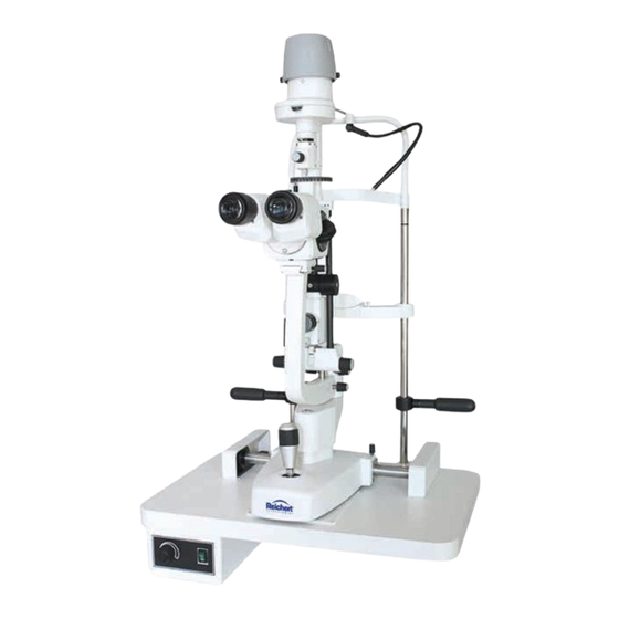
Features and Functions Parts Identification 1. On/Off Switch 2. Illumination Level Control 3. Glide Plate 4. Joystick for horizontal and vertical adjustment 5. Microscope Arm Lock-Knob 6. Slit Width Knob 7. Inclination Latch Release 8. Centering Knob 9. Breath Shield Mount 10. -
Page 9: Setup
Setup Unpacking and Installation 1. Open the outside shipping box and remove the four (4) inner boxes. 2. Remove the User's Guide and read it. 3. Open the box with the Table Top and Electronics in it. Refer to Figure SU-1. 4. - Page 10 Setup (continued) Unpacking and Installation (continued) 10. Using the 4mm Hex Wrench, adjust the Patient Handles by loosening the Screws that are Move securing them to the Chinrest Posts. Slide Handles Up the Patient Handles up or down to the desired or Down height, and secure them in place by tightening the Allen Cap Screws.
-
Page 11: Application Of Input Power
Setup (continued) Unpacking and Installation (continued) 15. Install the Base Assembly onto the tracks of the Table Top and slide the Guide Rail Covers around the tracks. Refer to Figure SU-12. 16. Attach the Base Lamp Wire to the back of the Slide Power Supply Assembly. -
Page 12: Instructions For Use
Instructions for Use Operation Focusing 1. Turn on the power using the On/Off switch located on the front of the Power Supply Assembly. Brightness can be adjusted by rotating the Illumination Level Control Knob. Refer to Figure SU-14. Note: The maximum intensity setting is for intermittent use only. -
Page 13: Adjusting Slit Length
Instructions for Use (continued) Operation (continued) Magnification 11. The angle between the illumination system and Dial the microscope can be varied between 0° and 90° to either the left or right. Refer to Figure IN-5. 12. The illumination angle is indicated on the Illumination Angle Scale on the slit lamp arm. -
Page 14: Slit Rotation
Instructions for Use (continued) Operation (continued) Slit Rotation Slit Rotation/ Slit Length Knob Rotation By grasping the Slit Rotation/Length Knob, the lamp Scale housing can be rotated. This, in turn, rotates the slit from vertical to horizontal in either direction. The slit positions are click-stopped in 45°... -
Page 15: Cleaning & Maintenance
Cleaning & Maintenance WARNING: RISK OF ELECTRIC SHOCK. ALWAYS DISCONNECT THE POWER CORD FROM THE WALL AND THE INSTRUMENT BEFORE PERFORMING ANY OF THE FOLLOWING CARE AND MAINTENANCE PROCEDURES. Cleaning External Cleaning Clean the external surfaces of this instrument using a clean, soft cloth moistened with a mild detergent solution (1 cc of liquid dish soap to one liter of clean, filtered water). -
Page 16: Changing The Halogen Lamp
UNTIL IT HAS COOLED AND USE GLOVES OR A THICK CLOTH WHEN HANDLING ANY HALOGEN LAMP. WARNING: REPLACE HALOGEN LAMP ONLY WITH Pull Up REICHERT P/N 15121 TO ENSURE PATIENT LIGHT LEVEL SAFETY. Two Screws Figure MM-3 Remove Cover WARNING: NEVER TOUCH A HALOGEN LAMP WITH BARE HANDS AS FINGERPRINTS WILL SHORTEN THE LAMP LIFE. -
Page 17: Fuse Replacement
Cleaning & Maintenance (continued) Fuse Replacement Replace the fuses in the Power Input Module with the fuses indicated in the Specifications section of this manual. Pull 1. Remove input power to the instrument. 2. Press down on the top tab in the middle of the Power Input Module to release the Fuse Holder, Tabs and gently pull out the Fuse Holder by gripping the... -
Page 18: Troubleshooting
Troubleshooting The following chart outlines some common issues with the Xcel 455 Slit Lamp and some steps you can take to correct the issue. If problems persist, please contact the Reichert as listed in the Introduction section of this manual. -
Page 19: Specifications
Specifications Catalog Number 15140 Physical Dimensions Size (From Tabletop): Weight, unpacked: 39.3 lbs (17.8 Kg) Height: 26.0 in. (66.0 cm) Weight, packed: 65 lbs (29.5 Kg) Width: 18.0 in. (45.7 cm) Depth: 13.5 in. (34.3 cm) Electrical Voltage: 100V-240 VAC Power Input (max): 56-73 VA Frequency: 50/60 Hz Fuses: Time-Lag (1.6A, 250V), 5x20 mm, (P/N RFAG20063) -
Page 20: Movement Ranges
Specifications (continued) Field of View Magnification Field of View (mm) 6.5 X 37.0 10 X 24.0 15.0 Movement Ranges Longitudinal (In/Out) 4.3 in. (110 mm ) Lateral (Left/Right) 4.3 in. (110 mm ) Vertical (Up/Down) 1.2 in. (30 mm ) Chinrest Range 2.8 in. -
Page 21: Guidance Tables
Guidance Tables Table 201 – Guidance and Manufacturer’s Declaration Electromagnetic Emissions All Equipment and Systems Guidance and Manufacturer’s Declaration – Electromagnetic Emissions The Xcel 455 is intended for use in the electromagnetic environment specified below. The customer or user of the Xcel 455 should ensure that it is used in such an environment . Electromagnetic Environment Emissions Test Compliance... - Page 22 Guidance Tables (continued) Table 202 – Guidance and Manufacturer’s Declaration Electromagnetic Immunity All Equipment and Systems Guidance and Manufacturer’s Declaration – Electromagnetic Immunity The Xcel 455 is intended for use in the electromagnetic environment specified below. The customer or user of the Xcel 455 should ensure that it is used in such an environment. Immunity IEC 60601 Compliance...
- Page 23 Guidance Tables (continued) Table 204 – Guidance and Manufacturer’s Declaration Electromagnetic Immunity Equipment and Systems that are NOT Life-supporting Guidance and Manufacturer’s Declaration – Electromagnetic Immunity The Xcel 455 is intended for use in the electromagnetic environment specified below. The customer or user of the Xcel 455 should ensure that it is used in such an environment.
- Page 24 Guidance Tables (continued) Table 206 – Recommended Separation Distances between Portable and Mobile RF Communications Equipment and the XCEL 455 for ME Equipment and ME Systems that are NOT Life-supporting. Guidance and Manufacturer’s Declaration - Electromagnetic Immunity Recommended Separation Distances between Portable and Mobile RF Communications Equipment and the Xcel 455 The Xcel 455 is intended for use in the electromagnetic environment in which radiated RF disturbances are controlled.
-
Page 25: Warranty
If notified promptly in writing of any action brought against the purchaser based on a claim that the instrument infringes a U.S. Patent, Reichert will defend such action at its expense and will pay costs and damages awarded in any such action, provided that Reichert shall have sole control of the defense of any such action with information and assistance (at Reichert’s expense) for such defense, and of all negotiation for the settlement and... - Page 26 Notes 15140-101 Rev. C...
- Page 27 Notes 15140-101 Rev. C...
- Page 28 3362 Walden Ave Depew, NY 14043 Toll Free: 888-849-8955 Phone: 716-686-4500 Fax: 716-686-4545 Email: reichert.information@ametek.com www.reichert.com AMETEK GmbH Business Unit Reichert Carl-von-Linde-Strasse 42 85716 Unterschleissheim/Munich Germany Email: info.reichert-de@ametek.com Tel: +49 (89) 315 8911 0 Fax: +49 (89) 315 891 99 ISO-9001/13485 Registered 15140-101 Rev.
Need help?
Do you have a question about the XCEL 455 and is the answer not in the manual?
Questions and answers