Table of Contents
Advertisement
Quick Links
Advertisement
Table of Contents

Related Manuals for diapath Galileo SEMI


Summary of Contents for diapath Galileo SEMI
- Page 1 Galileo SEMI Semi-automatic microtome User Manual...
- Page 2 Manufacturer: Diapath S.p.A. Via Savoldini,71 24057 Martinengo (BG) Italy Tel. (+39)0363.986.411 Fax (+39)0363.948.000 www.diapath.com info@diapath.com...
-
Page 3: Manual Information
Diapath S.p.A. has done as much as possible to assure the accuracy of this manual. However, in case something seems to be wrong or not clear, please contact Diapath S.p.A or the distributor. Diapath adopts continuously a development policy and reserves the right to make changes and improvements to any product described in this manual without prior notice. -
Page 4: Preface
The operators shall be adequately trained in its use and must respect all safety rules and its use limits. Instrument maintenance, due to trouble or malfunction, shall be performed by trained and authorized Diapath S.p.A. staff. The instrument complies with CISPR 11 Class A rules: in case of domestic use, it may cause radio interferences. - Page 5 • EN 61000-3-2(*): Electromagnetic compatibility (EMC) Part 3-2: Limits - Limits for harmonic current emissions. (equipment with input current <= 16A per phase). • EN 61000-3-3(*)+ A1(*)+ A2(*): Electromagnetic compatibility (EMC) Part 3-3: Limits - Limitation of voltage fluctuations and of flicker in low voltage supply systems for equipment with rated current <= 16A and not subject to conditional connection.
-
Page 6: Quality Control
Diapath S.p.A. tests its own products in accordance with some internal procedures, to reduce possibility of anomalies during the operation. To identify and to find out its own instruments, Diapath S.p.A. uses some internal procedures in which we can find production recording, assembling recording, tests recording, serial number or batch code and configuration recording. -
Page 7: Safety Information
Instructions of danger Never disassemble, modify or repair the instrument or one of its parts without written authorization by Diapath S.p.A. Do not use any kind of different power supply from the mentioned ones. For use at voltages higher than 125V in the North American market must be used electricity supply cables with NEMA 6-15P plug, C13 plug connector and STJ cable with nominal capacity 13A 250V. -
Page 8: Instructions Of Caution
After such training, the operators must have understood that: • The microtome must be connected to a voltage source in accordance with electrical data label. • The use of the microtome differently from Diapath instructions might compromise its functioning and the safety of the operator... -
Page 9: Definition Of Adopted Symbols
DEFINITION OF ADOPTED SYMBOLS In vitro diagnostic medical Electrical shocks risk device Manufacturer Foot switch connection Remote control Built in Conformity with CAN/CSA-C22.2 No 61010-1 requirements, Danger edition TUV certification Disposal European Community approval mark See the user manual RFID antenna... -
Page 10: Storage And Handling
STORAGE AND HANDLING For a correct conservation and functioning of the microtome, all the instructions provided in this manual concerning the maintenance and the installation shall be respected. Also the showed below environmental requirements shall be respected. Storage and transportation temperature range: da +5°C a +40°C Storage humidity: Working temperature range:... -
Page 11: Table Of Contents
SUMMARY MANUAL INFORMATION ........................3 Inspired to: ............................3 PREFACE ............................4 Destination of use ............................ 4 QUALITY CONTROL .......................... 6 SAFETY INFORMATION ........................7 Mentioned agreement and graphic symbols ..................7 Instructions of danger ..........................7 Instructions of caution ..........................8 Instructions of biohazard ......................... - Page 12 9.3 Cleaning the clamp .......................... 45 9.4 Cleaning the section waste tray ....................... 45 9.5 Replace fuses ........................... 46 TROUBLESHOOTING ........................47 WEEE DIRECTIVE ........................... 49 11.1 WEEE directives ..........................49 11.2 Warranty certificate ........................50...
-
Page 13: Instrument Placement And Installation
The instrument must be installed with a side distance from possible walls of at least one meter. 1.3 Startup ATTENTION Instrument placement and installation must be performed by Diapath S.p.A. trained and authorized staff. Perform the following installation steps: •... - Page 14 ATTENTION Instrument must be connected to a grounded power socket! DO NOT use extension cables ATTENTION The power cable plug disconnects the instrument from the electric system. Verify that the power cable plug is always easily accessible. Connecting Remote Control - Symbol The remote control connector is on the rear side of the instrument, identified by this symbol.
-
Page 15: Instrument Setting
INSTRUMENT SETTING 2.1 Before the use 2.1.1 Controls before the use It is a good practice to perform the following operations, before starting up the microtome: • Verify that the power cable is in good conditions. • Verify that the specimen holder can move freely up and down •... -
Page 16: Parts Of The Instrument
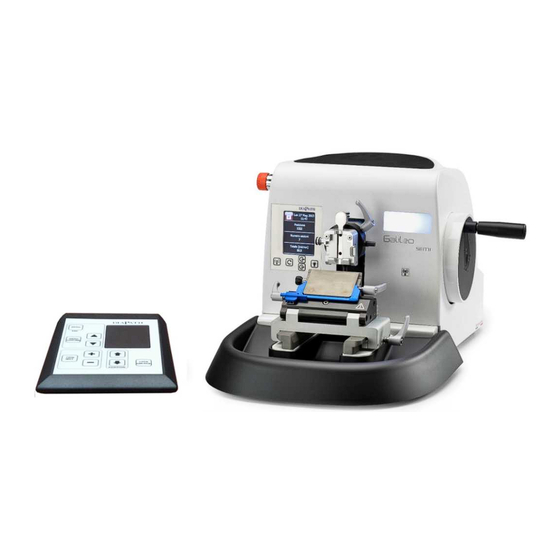
PARTS OF THE INSTRUMENT Directional specimen holder fixture with clamping system Emergency stop button Control panel Separate control panel Knife holder with knife guard Section waste tray Pic.1 - Parts of the microtome... -
Page 17: Directional Specimen Holder With Clamping System
3.1 Directional specimen holder with clamping system Head release lever for orientation Setscrews Cassette release lever Pic. 2 – Adjustable head To perform the orientation of the specimen: unlock the cassette tension lever, use setscrews for an appropriate orientation of the specimen, lock the lever. To mount the cassette in the clamp: push the lever and mount the specimen ATTENTION Specimen orientation must be performed only during the advancing phase. -
Page 18: Knife Holder
3.2 Knife holder 2-Knife guard with ejector 3-Clamping lever for the blade 1-Clamping lever for the lateral displacement 4-Clamping lever for knife holder base Pic. 3 - Knife holder To move the knife holder toward the specimen, release lever 4, mount it and lock the lever 4. To insert the blade, release the lever 3, push in the blade and lock lever 3. -
Page 19: Emergency Stop Switch
3.3 Emergency stop switch The emergency stop switch is on the left side of the microtome. The cutting motor stops immediately when the emergency stop switch is pressed. The specimen holder can be moved manually, allowing the user to operate for the safety. To restore microtome functionality, switch off the emergency stop switch and wait that the specimen holder has completed the positioning at the beginning of the horizontal feed (position 0). -
Page 20: Control Panel
3.5 Control panel Pic. 4 - Control panel The control panel displays the current operating mode, possible alarms and information. It displays also information about current cutting session: • Position of the specimen holder referring to horizontal feed; • Number of completed sections •... - Page 21 3.6 Control interface Pic. 5 - Control interface The control interface allows to set up microtome operating parameters. During operating are displayed the thickness values in micron during the Cutting/Trimming mode. Control interface has the following buttons: • LOCK/UNLOCK. When the microtome is in LOCKED mode, the movement is automatically locked •...
- Page 22 • If pressed, they allow to set up the section thickness. If the Trimming mode is ON is modified the Trimming thickness, otherwise the Cutting thickness. • MENU: press it to gain access to microtome configuration menu (see sect.5.2). Use the following buttons to surf the menu: To choose the entry of the menu To confirm (and save) the selected entry of the menu To exit from the current menu without saving...
-
Page 23: Control Panel Functionality
CONTROL PANEL FUNCTIONALITY 4.1 Main screen Thur 13 Sep 2012 11:45 Position Section No Cutting Pic.6 - Main screen After switching on the microtome using the power switch on the rear side, the control panel shows the main screen, similar to the one in the pic.5. The screen is divided in four sections: 1. -
Page 24: License Activation
4.2 License activation The activation is performed by RFID system: it is necessary to have the appropriated card. There are two licenses: • Limited license: the microtome is activated for a period of time, after which the coarse feed system is disabled. To reactivate the functioning, it is necessary to renew the license. •... - Page 25 Bring the card close to the RFID reader, situated under the lit window. When the card reader tracks the card, appears the following message: Thur 13 Sep 2012 11:45 Position Numero sezioni Please wait… Cutting Pic. 9 - Tracking card screen Keep the card close to the reader until appears the message confirming license activation: Thur 13 Sep 2012 11:45...
-
Page 26: Limited License Renewal
Possible error messages are: NON-VALID CARD The used card is not valid or already used. The license isn’t activated and RFID system is deactivated NON-VALID CARD TIMEOUT RFID reader didn’t track any card within 5 seconds from the activation. The license isn’t activated and RFID system is deactivated. - Page 27 2. Pressing again the button within 5 seconds the RFID system is activated. On display appears the following message: Thur 13 Sep 2012 11:45 Position Numero sezioni Place the card next to the reader Cutting Pic. 12 - RFID card message screen 3.
- Page 28 4. Keep the card close to the reader until appears the message confirming successful procedure: Thur 13 Sep 2012 11:45 Position Numero sezioni Starting up complete Cutting Pic. 14 - Successful new license starting up screen Possible error messages are: NON-VALID CARD The used card is not valid or already used.
-
Page 29: Log Card Creation
4.4 Log card creation The Galileo microtome RFID system allows to create a card containing the log of the operations carried out by the RFID system itself. Provide oneself with the appropriated card and proceed as follows: 1. Press the button (once if unlimited, twice if limited license) until appears the pop up with the following message: Thur 13 Sep 2012... - Page 30 3. Keep the card close to the reader until appears the message confirming log creation: Thur 13 Sep 2012 11:45 Position Numero sezioni Log writing complete Cutting Pic. 17 - Complete log codification screen Possible error messages are: NON-VALID CARD The used card is not valid or already used.
-
Page 31: Positioning Memory
4.5 Positioning memory buttons allow to manage positioning memory in order to have the possibility to bring the specimen holder to the stored position, to easily return to first cuttings position. Pressing the button the present position, on which the operator wants to return, is stored. A popup signals the successful position memorization: Thur 13 Sep 2012 11:45... - Page 32 To return to the stored position, press the button Thur 13 Sep 2012 11:45 Position Numero sezioni Positioning in progress Cutting Pic. 19 - Specimen holder under positioning screen When the specimen holder reaches the stored position, a confirmation message appears: Thur 13 Sep 2012 11:45 Position...
-
Page 33: Alarm Messages
4.6 Alarm messages If a functioning anomaly occurs, an alarm message appears in the pop-up: Thur 13 Sep 2012 11:45 Position Numero sezioni ALARM 802 FEED END Cutting Pic. 21 - End running alarm screen Alarm messages are the following (identification of each alarm by a 3 numbers code): ALARM 802 FEED END: The horizontal feed end has been reached (Position = 30000): the specimen holder can’t move anymore. - Page 34 ALARM 151 CONNECTION: a problem on communication protocol between electronic boards occurs. ALARM 151 CONNECTION ALARM 801 IN EMERGENCY: this message appears when emergency button is pressed. Unlocking it the message disappears. ALARM 801 IN EMERGENCY ALARM 750 EXPIRED LICENSE: the license of the microtome is expired and feed system is deactivated.
-
Page 35: Control Interface Functionality
CONTROL INTERFACE FUNCTIONALITY 5.1 Main screen Cutting Trimming 10.0 Pic. 22 - Main screen After switching the on microtome, using the rear power switch, the control interface displays the main screen, similar to the one in the picture above. The main screen displays the thickness of the section in micron during Cutting and Trimming mode. The mode ON is displayed in white color, the mode OFF in grey color. -
Page 36: Configuration Menu
5.2 Configuration menu Language Date & hour Information Retraction Pic. 23 - Configuration menu screen Press the button to enter configuration menu (see Pic. 23). ATTENTION It is possible to enter configuration menu only if system is in LOCKED mode Use the following buttons to surf the menu: •... -
Page 37: Setting Date And Hour
5.2.1 Setting date and hour Select the Date & hour entry in the configuration menu to enter the related menu: Date & hour Date 13/ 9/2012 Hour 11:45 Pic. 24 - Date & hour menu screen The two triangular symbols show which field between data or hour can be changed. Press the buttons to set up the value in the activated field. -
Page 38: Configuring Language
5.2.2 Configuring language Select the Language entry in the configuration menu to enter the related menu: Language Italiano English Español Français Deutsch Pic. 25 - Language setting screen Press the buttons to choose the language and press the button to confirm. -
Page 39: Configuring Retraction
5.2.3 Configuring retraction Select the Retraction entry in the configuration menu to enter the related menu: Retraction Pic. 26 - Configuration retraction screen Selecting the entry Off, the specimen holder don’t retract before vertical stroke. Select the entry On to enter the screen in which to set up the retraction value in micron. Retraction Value [micron] Pic. -
Page 40: Displaying Information Screen
Select Information entry in the configuration menu to enter the screen with microtome serial number (16 digits) and firmware version of each electronic sheet (C= control board, L= local board, R= remote board). Information Firmware version: 1.0.0 Serial number: 1234567890abcde www.diapath.com – info@diapath.com Pic. 28 - Information display screen... -
Page 41: Performances And Limitations
Diapath S.p.A. refuses any contractual and non-contractual responsibility for damages caused by any mistakes done working in the non-compliance of instructions given by the manufacturer. Diapath S.p.A. refuses any responsibility if the microtome is not connected to electrical systems according to the local regulations. -
Page 42: Specifics And Installation
SPECIFICS AND INSTALLATION Semi-automatic microtome Galileo SEMI Technical features Dimensions (WxDxH) 400x675x350 mm Weight 40 Kg Electrical features Supply voltage 115-230 V~ ±10% Frequency 50-60Hz Maximum power consumption 200VA Power cable type F(Schuko) – type B - type I Fuses F3.15 AL 250V... - Page 43 Technical features Cutting thickness setting range 0.5 - 100 micron 0.5 - 5 micron in 0.5 micron increments 5 - 20 micron in 1 micron increments 20 - 30 micron in 2 micron increments 30 - 60 micron in 5 micron increments 60 - 100 micron in 10 micron increments Trimming section thickness setting range 1 - 600 micron...
-
Page 44: Cleaning And Maintenance
CLEANING AND MAINTENANCE ATTENTION Before each action indicated below, switch the instrument off. ATTENTION We suggest using suitable individual protection media (gloves, masks, etc. according to the situations) to perform the cleaning safely. 8.1 LCD display cleaning To clean the display, use a screen detergent (in accordance with the instructions defined by the detergent manufacturer). -
Page 45: Scheduled Maintenance
SCHEDULED MAINTENANCE This chapter describes cleaning and inspections to be performed on the entire system. Maintenance plans need daily, monthly and six-month checks. Clean each part of the instrument at least once a week for a correct and lasting instrument use. ATTENTION Before cleaning, perform decontamination as specimens could be potentially infectious. -
Page 46: Replace Fuses
• Connect the power cable and switch the unit on See section “Troubleshooting” in case of functioning problems. If problem persists, contact Diapath or the local distributor. ATTENTION We suggest a preventive maintenance operation at least once in a year. -
Page 47: Troubleshooting
High blade consumption Possible cause Corrective action Adjust the cutting speed and/or section Too great of a cutting force was applied thickness If problems persist or are not described in the previous chart, contact Diapath S.p.A. or the local distributor. - Page 48 COMPLETE BODY GALILEO SEMI SDSMA9008 KNIFE HOLDER GALILEO MICROTOME SDSPL9001N SECTIONS HOLDER CLAMP SDSMA9015 SECTION WASTE TRAY GALILEO SDSMS0096 WIRED REMOTE CONTROL L GALILEO SEMI SDSMS9033 COMPLETE ELECTRONIC SHEET GALILEO UL SDSMA9059 COMPLETE ELECTRONIC SHEET GALILEO SDSMA9006N MOTOR ROTATION ASSEMBLY SDSMA9012...
-
Page 49: Weee Directive
Diapath S.p.A. is an ecor’it member, global system of WEEE management (electronic and electrical equipment waste) home and professional in the Italian territory. -
Page 50: Warranty Certificate
11.2 Warranty certificate... - Page 51 Diapath S.p.A. Via Savoldini,71 24057 Martinengo (BG) Italy Tel. (+39)0363.986.411 Fax (+39)0363.948.000 www.diapath.com info@diapath.com...
Need help?
Do you have a question about the Galileo SEMI and is the answer not in the manual?
Questions and answers