
Summary of Contents for Dielectric 2200ST SmartTech Modular Dehydrator
- Page 1 SmartTech Modular Dehydrator 22000ST/33000ST Instruction and operation manual MODELS 2200ST / 33000ST SMARTTECH MODULAR DEHYDRATOR IB-430 REV. H PART NUMBER 100436...
- Page 2 3. Heed all warnings, cautions and notes. 4. Do not block any ventilation openings. 5. Install in accordance with SPX Dielectric instructions 6. Do not defeat the safety purpose of the grounding type plug 7. Protect the power cord from being walked on or pinched.
- Page 3 FCC Part 15 Class B Notice NOTE: This equipment has been tested and found to comply with the limits for a Class B digital device, pursuant to part 15 of the FCC rules. These limits are designed to provide reasonable protection against harmful interference in a residential installation.
-
Page 4: Table Of Contents
TABLE I TABLE OF CONTENTS SECTION TITLE PAGE Introduction Feature Descriptions Display Module Sensor Module Alarm/ATS Module Cabinet Features Compressor Heatless Dryer Humidity Sensor Passive Air Intake System Pressure Control 2.10 Water System 2.11 Optional Water Chiller Description of Operation Receiving and Inspection Location Considerations and Recommendations Installation... - Page 5 Figure No. Figure Description Page Front view cover Air/Water Flow Schematic Front view Side view, cabinet open Electrical enclosure Rear view Inside View Heat Exchanger/Fan Compartment Heatless Dryer Purge Solenoid Valves Table Table Description Page Table of Contents iv, v Table of Leading Particulars Appendix Description...
- Page 6 TABLE II TABLE OF LEADING PARTICULARS* C HAR ACT E RI S TI C M O DE L 2 2 0 0 0 S T MO D E L 3 3 0 0 0 S T Maximum Output 22,000 SCFD (25960 liters/hour) 33,000 SCFD (38935 liters/hour) Compressor DC12ST (2 per)
-
Page 7: Introduction
Section 2 will of the alarm condition. introduce you to the major improvements of the design. For those familiar with the Dielectric C.O. 2.1.2 Four softkey buttons are used to interface with dehydrators, Section 2 will refresh your memory... -
Page 8: Sensor Module
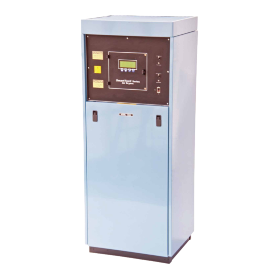
2.2 SENSOR MODULE 2.4 CABINET FEATURES 2.2.1 The Sensor Module measures the System 2.4.1 The lower front panel of the Dehydrator is Pressure, Line Pressure, Air Flow, Humidity, and removed by lifting and then turning the two latches. Incoming Voltage with its onboard sensors. External Each side panel is held by four screws at the rear of sensors for Low Water, High Water, and Water Tem- the cabinet. -
Page 9: Heatless Dryer
2.8.1 The Passive Air Intake is designed specifically should be returned to Dielectric for repair. for use in central office dehydrators. It performs 2.5.4 Repair kits are easy to install when needed several helpful functions and has no moving parts, requires no maintenance or adjustment. -
Page 10: Water System
unable to maintain a low dew point, no matter what the front cover is removed. The switch is clearly drying method is used. labeled and is located on the left side above the air intake filter. 2.9.2 The Models 22000ST and 33000ST contain a System Controller which maintains the correct 2.11 OPTIONAL WATER CHILLER (P/N System Pressure over the full outlet capacity of the... - Page 11 1) INTAKE FILTER 2) INTAKE DEFUSER 3) AIR COMPRESSORS 4) WATER SEPARATOR 5) HIGH WATER SHUT-OFF FLOAT 6) LOW WATER SHUT-OFF FLOAT 7) WATER EJECT FLOAT 8) WATER DRAIN PETCOCK 9) WATER EJECT SOL. VALVE 10) WATER EJECT OUTLET PORT 11) DRYING TOWER INLET PORT 12) DRYING TOWER OUTLET PORT 13) DRYING TOWERS...
-
Page 12: Receiving And Inspection
tank without any restriction. Inside the separator 3.8 Dry air flows from the heatless dryer outlet to tank, centrifugal action and large surface impinge- the System Controller, which has a single pressure ment separate the water from the air stream without adjust ment. -
Page 13: Installation
NOTE: Do not position of rustproof brass quick connect, automatic shut-off, the Air Dryer so that it is difficult to operate the couplings (available from Dielectric) together with disconnecting device. flexible hose is recommended. Provide safeguards against crimping, freezing and drain-back as in- For 22000ST..208-240V, 26.3-22.9A, 60Hz, 1 Ph... - Page 14 tion). Two check valves with hex nipple fittings come packaged with the Air Dryer. If using only 6.6.2 Instruction for Model 33000ST only: The Model 33000ST operates on 208/240 VAC, 3 one Air Outlet, install the Check Valve marked with P/N 47744 Flow Restrictor Check Valve label at Ph.
-
Page 15: Preparation And Start Up
6.9 Segregated alarm connections are provided on Verify that the power supply to the dehydrator is a labeled terminal board on the rear of the cabinet. The output of this terminal board is dry contact, factory configured for close in alarm indication of 7.3 Check to assure that the petcock (42) below the each alarm function of the dehydrator, as indicated. -
Page 16: Setting And Adjustment Procedures
Green/Yellow); RUNNING (LED solid green). Water Eject Float begins to rise (the middle float in the sight tube) and verify the lowering of the water The display will scroll the dryers operating pa- level as water is ejected out through the Water Eject rameters of System Pressure, Line Pressure, Flow, Solenoid Valve (8). - Page 17 the right arrow to select the YEAR. Use the UP and press OK. Select HIGH FLOW RATE and press DOWN arrow to change YEAR. Press OK when OK. Use the UP and DOWN arrows to increase done. Dashed line below the digits indicates selec- and decrease the flow increments of 1000 SCFD.
-
Page 18: Scheduled Maintenance
8.8 ADJUSTING THE SYSTEM PRESSURE 9.0 SCHEDUlED MAINTENANCE 8.8.1 The System Pressure Regulator (28) is located NOTE: A 12-month scheduled maintenance kit, part on the horizontal frame member. Before adjusting, wait number 100495 contains only the filters needed for until the front LCD displays the SYSTEM pressure each full year of operation. -
Page 19: Maintenance Procedures
on/off switch. Remove the water fill fitting from the compressor to the passive air intake is full. Install the passive air intake and add about one gallon of the water fill fitting back onto the passive air intake. water to the system. Replace the water fill fitting 11.4.4 Reconnect the electrical service to the to the passive air intake. - Page 20 11.5.5 Restore the coil assem bly and reconnect the 11.7.3 Loosen the quick release knob, disconnect the coil wires to the harness receptacles. motor electrical connector and slide the compressor forward to remove. 11.6 ClEANING WATER SIGHT 11.7.4 Follow the procedure described in the ASSEMBlY (Perform 11.1 first) compressor manual (P/N 10837), to rebuild the compressor.
-
Page 21: Alarms And Troubleshooting
If not, call the 12.4.1 To Clear and Reset an Alarm from the Display, Dielectric Technical Support Department with Model press MENU, choose RESET DRYER ALARM, and date of Manufacture for additional support. -
Page 22: High And Low Water Shutdown Alarm
12.5 HIGH AND lOW WATER 12.5.4 If the water loss continues, look for a leak SHUTDOWN AlARM at the drain outlet fitting. Check for leaks under the compressor (25), under the Separator Tank (35), 12.5.1 High and Low Water Shutdown may result Water Filter (39), Water Sight Tube (24), Passive from an incorrect water level or from a component Air Intake (32) and finally in the Heat Exchanger... -
Page 23: Compressor Circuit Breaker Alarm
12.8 POWER lOSS/BROWNOUT FAUlT the end of the water return line. Use a piece of small wire or a pipe cleaner to clean the Water Metering AlARM Orifices. 12.8.1 The Power Loss Alarm will be displayed if 12.6.6 A Low Temperature Shutdown will occur there is a low voltage condition or complete loss of electrical service. - Page 24 12.9.2 If there is a Humidity Alarm, the Display will from the electrical service and check the Purge Valve first indicate the Time and Date of the Alarm, and show coils (7) by measuring the coil resistance while a Minor Alarm (Blinking Green/Red LED). If after 5 disconnected from the dehydrator elect rical harness.
-
Page 25: Low System Pressure Shutdown Alarm
12.11 HIGH SYSTEM PRESSURE 12.9.10 If the Purge Flow is low (this is the portion of the dry air that is required from the drying tower SHUTDOWN AlARM to regenerate the off-line tower) then a humidity 12.11.1 The High System Pressure alarm will alarm will likely occur. -
Page 26: High Line Pressure Alarm
12.13 HIGH lINE PRESSURE AlARM 13.5 Remove the CO#1 and CO#2 Alarm connectors from the Alarm/ATS Interface Module and reposition 12.13.1 The High Line Pressure alarm will occur them on the CO backup connections located directly should the line pressure rise above its set pressure. above. -
Page 27: Parts List For 22000St And 33000St Models 21
Parts List for 22000ST and 33000ST Models ITEM PART NUMBER DESCRIPTION QUANTITY 100633 Cabinet side panel (replacement) 100632 Cabinet front door (replacement) 99045 LCD display board 100529 Sensor control board (programmed) 100530 Alarm/ATS interface board (programmed) 64904 Backup Battery 3V 0005385013 1-1/2 Amp Fuse Fast Acting 97901... - Page 28 Parts List for 22000ST and 33000ST Models (continued) ITEM PART NUMBER DESCRIPTION QUANTITY 101215 Heatless dryer assembly (22000ST) 101216 Heatless dryer assembly (33000ST) 46221 Water filter housing 46222 Water filter element 0014000237 Water filter housing o-ring 10338 Water separator drain petcock 104283 Metering nozzle “E”...
- Page 30 (28) (29) (44) (18) (30) (36) (31) (37) (32) (35) (42) (33 & 34) (19, 20, 21, 22, 23, 24) (39, 40, 41) (38) (25, 26, (43) 27, 43) (25) Figure 4 Side View, Cabinet Open...
- Page 31 (13) (14) (15) (15A) (15A) (16) Figure 5, Electrical Enclosure...
- Page 32 (46) (not shown) CO Alarm Manual Operation Switch Back up (normally off) CO Alarms Segregated ATS 300 Alarm Hookup Hook up High Pressure Water Outlet 3/4" FPT Drain Low Pressure Outlet 3/4" FPT Power Entrance Terminal Block Cabinet Grounds (46) (not shown) Figure 7, Rear View...
- Page 33 Figure 8 Inside View...
- Page 34 (11A) Figure 9 Heat Exchanger/Fan Compartment...
- Page 35 Outlet Replacement Parts For Heatless Dryer Spare Upper Center Block P/N 100639 (22000ST) Spare Upper Center Block P/N 100638 (33000ST) Spare Lower Center Block P/N 53070 Check Ball P/N 15903-008 Figure 10, Heatless Dryer (typical) Intake Figure 11, Purge Solenoid Valve...
- Page 36 APPENDIX A (Alarm Connection Wiring)
- Page 37 APPENDIX A (Alarm/ATS Interface Board)
- Page 38 APPENDIX A (Sensor Board)
- Page 39 APPENDIX C (Front Panel Display Features) Dryer Status/ Alarm Indicator Left Compressor Circuit Breaker 40 Character/ 4 Line Backlit Right Compressor Display Circuit Breaker Power ON/OFF Switch Exit/Help Enter/OK Multifunction Multifunction Push button Push button Push button Push button...
- Page 40 APPENDIX C (SmartTech Menu Block Diagram)
- Page 41 APPENDIX C (Setup Menu Block Diagram) Setup Menu Block Diagram MENU SETUP Current Current Power On Low Line High Line High Flow ATS Bus Time Date Delay Pressure Pressure Rate Brownout Address Selection of A1-A8, B1-B8, C1-C8, D1-D8, and E1-E8...
- Page 42 APPENDIX D (Wiring Electrical Schematic)
- Page 43 Incoming AC Lines NOTE: 1.5 amp fuse is a ¼ x 1-1/4 “ fast acting type 3AG or equivalent. Dielectric P/N 0005385013 The LEDs adjacent to F1, F2, F3, and F4 indicate that the fuse is good and not blown. If not ON, first check for CB5 and CB6 not tripped.
- Page 44 APPENDIX F (SmartTech Alarms) Alarm Classifications Major Alarms are those alarms that will cause the Air Dryer to Shut Down and become registered at the CO Terminal Block These alarms are Low and High System Pressure, Low and High Water level, Low and High Water Temperature, Circuit Breaker, Power Loss and Humidity ( Minor first then Major after the 5 minute shutdown delay) Minor Alarms are those alarms that will allow uninterrupted Dryer operation and become registered at...
- Page 45 A Power Loss Major Alarm occurs when the voltage drops below the Brown-Out level for any phase. The factory setting is 180Volts. Upon Start-up, there is a no disarm period. There is no Time Lag before the alarm becomes registered at the CO and Segregated Terminal Blocks. Alarm resetting is automatic and upon clearing the dryer will enter a standby mode, and will delay for the “power-on delay”...
- Page 46 APPENDIX G (Power Termination and Grounding)
- Page 47 Fahrenheit and Celsius scales are numerically equal. Heatless Dryer: A dryer design of Dielectric which describes the most simple and effi cient heatless air dryer. A dryer consists of two desiccant towers, two maintenance free ball checks and two direct acting solenoid valves controlled by a solid state timer.
- Page 48 Tel: +44 (0) 117 976 7776 Fax: +44 (0) 117 976 7775 rd.sales.uk@spx.com www.radiodetection.com © 2017 Radiodetection Ltd. All rights reserved. Radiodetection is a subsidiary of SPX Corporation. Dielectric is a trademark of Radiodetection in the United States and/or other countries.
Need help?
Do you have a question about the 2200ST SmartTech Modular Dehydrator and is the answer not in the manual?
Questions and answers