
Summary of Contents for Rocketronics ELS 4 Basic
- Page 1 ELS 4 BaSic Operating instructions TrAnSLATIon of ThE orIgInAL ENGLISH opErATIng InSTruCTIonS This manual describes the commissioning and use of the cycle controller ELS 4 BASIC.
- Page 3 The distribution and reproduction of this document, its use and communication of its con- tents is strictly prohibited. not permitted, unless expressly conceded. Contraventions obligate to Compensation. All rights in the event of patent grant or utility model registration. reserved. All product designations mentioned in this manual are trademarks of respective companies.
-
Page 4: Table Of Contents
CONTENTS .......................... 4 Disclaimer ..................... 4 Addressee of the documentation ........................ 4 Safety instructions ...... 5 Licence conditions for software of the electronic leadscrew control system Notes ............................ 6 Scope of delivery and accessories .................. 10 Basic requirements ....................... 11 .......................... - Page 5 Basic functionality ......................... 52 ..................... 54 Selection of cutting passes Possible cycles ........................ 55 ........................ 56 GEARBOX LEFT ........................ 56 GEARBOX RIGHT .......................... 58 TURNING .......................... 62 BORING .......................... 64 FACING .......................... 66 PARTING .......................... 67 UNDERCUT ........................ 69 MAKING THREADS ........................
-
Page 6: Disclaimer
DISCLAIMER We have checked the contents of this publication for conformity with the hardware and soft- ware described. Nevertheless, deviations cannot be excluded, so that we do not assume any liability for the complete conformity. However, the information in this publication is checked regularly and necessary corrections are included in the following editions. -
Page 7: Licence Conditions For Software Of The Electronic Leadscrew Control System
LICENCE CONDITIONS FOR SOFTWARE OF THE ELECTRONIC LEADSCREW CONTROL SYSTEM In the following the company Rocketronics.de, owner Louis Schreyer is referred to as „LICENSER“ of the software. I. Rights of Use 1. The LICENSER grants to the Customer a royalty-free, perpetual and non-exclusive right to use (license) the SOFT- WARE contained in this archive (hereinafter referred to as „SOFTWARE“). -
Page 8: Notes
NOTES The ELS controls are simple cycle controls that allow fully automatic cycle machining with a conventional lathe. For this purpose, drives must be mounted on the axes of the ma- chine and a rotary encoder for position feedback must be mounted on the main spindle. Equipped with these components, the machine can then be controlled in 2 axes. - Page 9 All products containing a component part manufactured by Rocketronics must include appropriate warnings and instructions for safe use and operation when handed over to the end user. All warnings provided by Rocketronics must be passed directly to the end user.
- Page 10 Qualified personnel Qualified personnel must be able to correctly interpret and implement the safety instructions and warnings. They must also be familiar with the safety concepts of automation technology and have received appropriate training. Non-qualified interventions in the devices or failure to observe the warning notices in this documentation or the warning notices displayed by the device may result in damage to property or personal injury.
- Page 11 ● Switch off the device immediately if it shows noticeable deviations from normal operation. ● Rocketronics.de guarantees the proper function of the device only if no changes are made ● in mechanics, electronics and software. The opening of the device as well as adjustment, maintenance and repair work may be ●...
-
Page 12: Scope Of Delivery And Accessories
SCOPE OF DELIVERY AND ACCESSORIES The scope of delivery of the ELS Basic includes a control unit. Various components are available as accessories. Manual ELS Basic This Manual Lathecontroller Basic- OPTIONAL OPTIONAL OPTIONAL Wallmount Micro-SD-Card Power supply 12V/1A 2 GB Micro-SD-Card for Typ WH-ELSBW Power supply with 12V und Adjustable wall mount... -
Page 13: Basic Requirements
BASIC REqUIREMENTS Lathe The machine must have a lead screw and a cross slide. It must be possible to equip these spindles with drive motors. Simple so-called mechanic lathes are therefore not optimally suitable. The size is not limited. Rotary encoder on main spindle Make sure that an encoder with quadrature signals is connected to the main spindle. -
Page 14: Encoder
The pulse rate delivered to the ELS per spindle revolution must be entered in the control ● settings before starting operation. Encoders can be connected directly to terminals or via the Rocketronics „Incremental Line ● Driver“ with an Ethernet patch cable (CAT5 or better, S-FTP e.g.) to the RJ45 connector. See... - Page 15 Encoders either have a fixed pulse rate or can be set. Additional Resources: Product Page 3D Model The frequently used adjustable encoder type AMT 103-V has 4 small switches to set the pulse CUI Inc │ SERIES: AMT10 │ DESCRIPTION: MODULAR INCREMENTAL ENCODER date 10/10/2018 │...
-
Page 16: Axle Drives
AXLE DRIVES Drive motors must be mounted on the X and Z axes. ● ● In order to be able to move the axes, the installed threaded spindles must be moved using stepper or servo motors. These are available in various sizes which must be selected to suit the machine. - Page 17 ed. All in all a very recommendable drive for the ELS. The disadvantage here, too, is the higher price. The ELS generates step and direction signals for motor drivers. A step pulse drives the stepper motor 1/200 revolution further, the direction signal determines in which direction the motor rotates.
-
Page 18: Selection Of Right Motor
SELECTION OF RIGHT MOTOR The stepper motor must provide sufficient torque to turn the lead screw in all positions. De- pending on the machine, more or less power is required. In general it can be said that the nec- essary forces are smaller than e.g. on a milling machine. For normal hobby machines with 400-600mm distance a Nema24 motor with 3-4A current should be sufficient. -
Page 19: Maximum Feed Speed
MAXIMUM FEED SPEED The maximum feed rate in mm/revolution is directly linked to the ratio of encoder pulses, mo- tor steps/revolution and the thread pitch of the lead screw. The maximum feed rate is decisive for the maximum thread pitch you can produce. Please note, however, that threads with a pitch of more than 8 mm are very rarely turned. - Page 20 The maximum feed speed is: Fmax = (4 x Encoderimpulses x Leadscrewpitch) / Motorsteps Example: Encoderimpulses: 400 Impulses/rev Motorsteps: 400 Steps/rev Leadscrewpitch: Fmax = (4 x 400 x 4) / 400 = 6400/400 = 16mm / rev If you now set a reduction ratio of 1:2, you halve Fmax. This can be compensated by using 800 instead of 400 encoder pulses or by halving the steps of the motor, i.e.
-
Page 21: Motor-Drivers
MOTOR-DRIVERS To convert the control signals supplied by the ELS into motor current, we need a motor driv- er or motor output stage. These are small electronic devices that generate suitable signals to move the motor. Most types have step and direction inputs, 4 output terminals for the motor connection and +VDC and GND connections for the supply volt- age. -
Page 22: Emergency-Stop
This should be activated. Please refer to the documentation of the manufacturers of the com- ponents. All components purchased from Rocketronics are accom- panied by corresponding documentation and pin assignments! -
Page 24: Controlelements
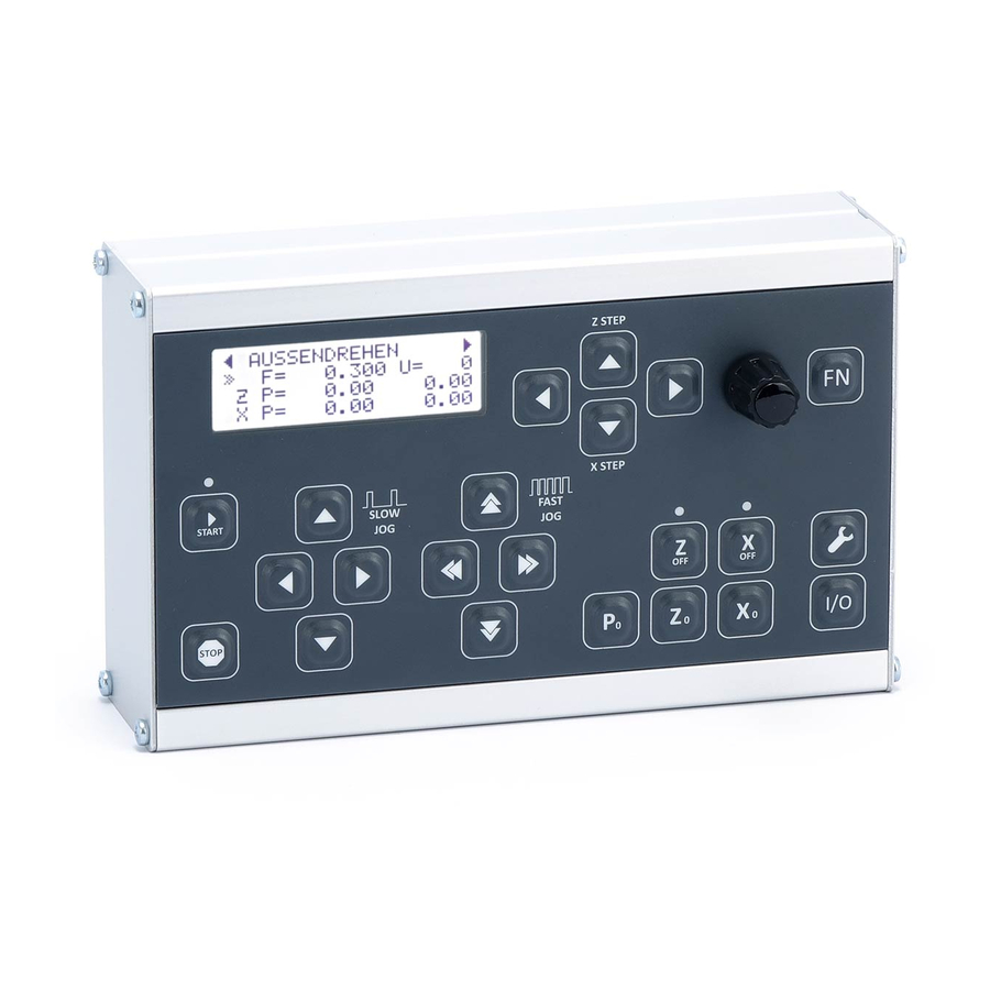
CONTROLELEMENTS FRONT SIDE The ELS keyboard has buttons for operation. In addition there are 3 LEDs in the keyboard, which are used to indicate states. In the manual, buttons are addressed with a symbol, e.g. START, and with the following designation: (Z-STEP) LEFT START... -
Page 25: Key Functions
KEY FUNCTIONS START Start of a cycle. The LED above lights up when a cycle is active. Most cycles do not start until the spindle is already turning! STOP Stops a running cycle. Sets the selected input value to 0, e.g. feed rate, ZP or XP. Sets the current Z position to 0, zeros the axis. -
Page 26: Display-Elements
DISPLAY-ELEMENTS The LCD display shows the data on 4 lines. The standard display before the start of a cycle shows the basic data. The display changes depending on the mode. Selected mode CURRENT X POSITION XP= X ENDPOSITION CURRENT Z POSITION ZP= Z ENDPOSITION CURSOR F= FEED in mm/U... -
Page 27: Micro-Sd-Card-Slot
MICRO-SD-CARD-SLOT The slot for a micro SD card is located on the right side of the housing. Such a memory card can be used to update the software of the controller. Thus a simple update without PC is necessary, directly at the installation location. See software update. Commercially available memory cards of 2-32GB with FAT32 formatting are compatible. -
Page 28: Inputs And Outputs
INPUTS AND OUTPUTS Various inputs and outputs are available for connection to the machine. 2 inputs for 1 incremental encoder (RJ45 and screw terminal) 2 inputs for 1 X-axis drive system (RJ45 and screw terminal) 2 inputs for 1 X-axis drive system (RJ45 and screw terminal) (ATTENTION: Either use RJ45 -OR- terminals, not both!) 1 supply voltage input for 12V round plug 4 digital inputs for emergency stop circuit, limit switches and error signals... -
Page 29: Screwterminal Data
SCREWTERMINAL DATA The screw terminals are pluggable and can accept cables with the following cross-sections: Solid (rigid) 0.14 mm² - 1.5 mm² AWG 28-16 Flexible 0.14 mm² - 1.5 mm² AWG 28-16 Flexible with wire end sleeve 0.25 mm² - 1.0 mm² Stripping length: 7.0 mm Maximum current:... -
Page 30: Connection Of Encoder
To ensure the interference immunity of the signals, the signal must be transmitted differential- ly, recognisable by the connections A+, A-, B+ and B-. Normal signals can be converted into a differential signal with the Rocketronics „differential line driver“. An index signal is not neces- sary and is not used. - Page 31 Encoder connection to differential line driver Many encoders deliver only one non-differential signal, which has many disadvantages. To con- vert it into a differential signal you can use the differential line driver. This converts the AB signal into an A+A-B+B signal and thus significantly increases interference immunity. Another advantage of the driver is the possibility of connecting the encoder to the controller via a com- mercially available Ethernet patch cable.
-
Page 32: Connection Motordriver
Connection: Use either screw terminals or RJ45 jack for connection. The RJ45 connector is compatible with Rocketronics RJ45 driver adapters and allows clean connection of motor drivers with commer- cially available Ethernet patch cables. Terminal assignment screw terminal for X and Z axis:... - Page 33 Pin assignment RJ45 socket for X and Z axis: We offer small adapters for easy connection of leadshine drivers (and copies thereof). These are connected directly to the driver connectors and then provide a suitable RJ45 connector. Connect drivers and controls with an Ethernet patch cable very simple and create a clean and shielded connection.
-
Page 34: Digital Inputs
DIGITAL INPUTS The controller has 4 digital inputs that can be loaded with up to 12V. For easy connection, 12V is available next to each input terminal. If external power supplies are used, the earth terminals next to the input terminals can be used for the earth connection between the power supply and the controller. -
Page 35: Emergency Stop
EMERGENCY STOP The controller must be integrated into an emergency stop circuit in order to implement an emergency stop function. DANGER A non-existent or malfunctioning emergency stop circuit can result in death or serious injury. Ensure that the entire machine is in a safe state in the event of an emergency stop before using or handing over the machine. - Page 36 Input 3: Z LIM The input must be activated in the settings! Input for limit switch of the Z axis. You can use potential-free contacts of a mechanical limit switch or inductive proximity switches (see below) When the input is activated, the control switches to a safe state and ends running cycles until a release has been given with the STOP key.
-
Page 37: Digital Outputs
DIGITAL OUTPUTS The controller has 4 digital outputs which can be used for control purposes. Output voltage: Identical with voltage at OUTPOW IN, maximum 24VMaximum output current: 500mA per outputAll outputs are short-circuit proof and equipped with free-wheeling diodes. Resistive and inductive loads can be switched. The output stages switch DC voltage which is applied to OUTPOW IN. - Page 38 Output 3: COOL This output is activated at the start of a cycle and can start cooling. A waiting time between ac- tivation of cooling and start of cutting can be set in the settings. This ensures that the coolant has reached the tool before the cut starts.
-
Page 39: Grounding, Cable And Shielding
GROUNDING, CABLE AND SHIELDING Use cables of sufficient length, but shorten overlong cables if possible. The cross-section of the cables should be sufficiently dimensioned, especially the cables between driver and motor, where high currents flow. 1.0 mm reaches up to 10A current 1.5 mm reaches up to 15A current 2.5 mm... -
Page 40: System Connection Diagram
SYSTEM CONNECTION DIAGRAM The system consists of controller, motor systems, encoder, power supply units and safety ele- ments is wired as shown below (schematically shown).. Encoders and motor drivers can be connected directly with patch cables as well as with mul- ti-core cables. -
Page 41: Setup
•Z LIMIT ACTIVE? SETUP •Z LIMIT POLARITY INPUTS •ERROR ACTIVE? •ERROR POLARIY •SPINDLE STOP ACTIVE? •SPINDLE STOP SWITCH DURATION •ESTOP-FOLLOW ACTIVE? •ESTOP-FOLLOW DELAY SETUP •COOL ACTIVE? OUTPUTS •COOL DELAY •I/O INFORMATION INPUTS OUTPUTS •FIRMWARE VERSION ELS 4 BASIC SETUP •SELFTEST RESULT INFORMATION... -
Page 42: Setup General
SETUP GENERAL Element Description LANGUAGE Language selection, German or English WAITING TIME BEFORE RE- Only for 1-axis operation: This is the time that is waited in TURN automatic mode after reaching an end position until the carriage returns to 0. During this time, the stylus must be pulled back manually, otherwise an already cut thread will be destroyed. -
Page 43: Setup Z-Motor
SETUP Z-MOTOR Element Description Spindle pitch This is the pitch of the lead screw of the machine. In case of doubt, this must be remeasured. Backlash The backlash of the sled. Those who do not have an exact ball screw on their lathe will almost certainly have a back- lash. -
Page 44: Setup X-Motor
SETUP X-MOTOR Element Description Spindle pitch This is the pitch of the lead screw of the machine. In case of doubt, this must be remeasured. Backlash The backlash of the sled. Those who do not have an exact ball screw on their lathe will almost certainly have a back- lash. -
Page 45: Setup Data
SETUP DATA Element Description Step Size Fine The step size in mm that is moved during the large step-by- step movement of the axes. In the step mode of the X or Z axis, the rotary knob must be turned WITHOUT the knob being pressed. -
Page 46: Setup Inputs
SETUP INPUTS Element Description ESTOP Input active Input for emergency stop circuit, switch or relay contacts ESTOP Activate or deactivate input ESTOP Input polarity Standard: Open Active (NC). Can be set to Closed Active (NO). X LIMIT Input active Input for X limit switch Activate or deactivate limit switch input X LIMIT Input polarity Standard: Closed Active (NO). -
Page 47: Setup Outputs
SETUP OUTPUTS Element Description Spindle Stop active Activate output for spindle stop signal (NO contact). The output becomes active at the end of a cycle or on abort. Spindle Stop switch dura- Duration of the switching signal in milliseconds tion ESTOP-FOLLOW active Output following ESTOP input. -
Page 48: Commissioning
COMMISSIONING PREPARATIONS Mounting the control Mount the controller on the wall, a support or on the machine so that you can operate the keys without moving the case. Optionally, you can purchase a suitable wall mount bracket for the ELS Basic. Connection Connect the emergency stop circuit, the motor output stages and the encoder to the rear terminals. -
Page 49: Checklist Before Commissioning
CHECKLIST BEFORE COMMISSIONING To facilitate commissioning, please check the following items in advance: The pulse rate of the encoder must be set correctly on the encoder, 400 pulses per spindle revolution are usually optimal. This pulse rate must also be adopted in the settings of the ELS (SETTINGS -> SETUP ENCODER ->... -
Page 50: Implementation Of The Commissioning
IMPLEMENTATION OF THE COMMISSIONING Please make sure that the motor and encoder parameters are correctly set in the settings be- fore proceeding. The correct number of steps of the motors and the correct pulse rate of the encoder must be set. DANGER When moving, make sure that there is enough free travel so that the machine is not damaged! Use all protective measures of the machine as prescribed... - Page 51 -> Now snap the lock nut into place! If the spindle turns to the left, the slide should move in the direction of the chuck. If it does not, the encoder is set the wrong way round. Remedy: Switch to SETTINGS -> SETUP ENCODER -> REVERSE DIRECTION and change the direc- tion there.
- Page 52 If you have any problems, please feel free to contact us at info@rocketronics.de . It is best to write down the setting values as well..
- Page 53 What to do if the measured path deviates from the set path? Small deviations of a few hundredths are normal, because the spindles are more or less accu- rate, and even ex works their deviations can have. If the deviation to 50 mm is more than 0.1 mm, something is wrong, check: ●...
-
Page 54: Basic Functionality
BASIC FUNCTIONALITY The Electronic Leadscrew Control (ELS) is a cycle control for lathes and allows the automatic execution of turning operations and the free selection of the feed rate. Relative travel distances In contrast to many industrial controls, the ELS operates in a relative mode: The operation to be performed always starts from the zero point of the tool, i.e. - Page 55 The button also has a push-button function: to fine-tune the increment of the changes, you can also press the push-button down before turning, it also has a push-button function. For further refinement, press the FN key and then rotate. So you can enter in steps of 1.0, 0.1, 0.01 and in some places also 0.001.
-
Page 56: Selection Of Cutting Passes
General information on the cycles Before each operation, it is necessary to correctly set the X and Z axis zero points and check ● the entered feedrate, XP and ZP values. Before each operation, a release by START is necessary, also in the gearbox modes. ●... -
Page 57: Possible Cycles
Tip 1: The number of passes can also be turned to 1, then 1x to full depth. This is useful if you want to turn to full depth again, e.g. when threading to remove the last hundreds of the material from the thread groove. -
Page 58: Gearbox Left
GEARBOX LEFT Electronic gear with freely selectable feed rate. The motor is driven at the set feed rate, the spindle stops -> the motor also stops. This is identical with the condition before the conversion of the machine, the gear is now replaced by the ELS. If the spindle turns to the left, the carriage moves to the left, if the spindle turns to the right, the carriage moves to the right. -
Page 60: Turning
TURNING Straight chip removal in the longitudinal direction towards the chuck to reduce the diameter of a workpiece. Moving axes and directions: • X towards the chuck (-X) • Z towards the chuck (-Z) Required data: • Feed F in mm/U •... - Page 61 IMPORTANT: ALWAYS MAKE SURE THAT THE ZERO POINT IS SET CORRECTLY! There are three possible variants: ZP = 0 and XP = 0 In this case, the movement after the START signal goes after a safety query to X 0,00 and then in -Z direction until the STOP key is pressed. START-STOP operation is possible while the vehicle is moving.
- Page 62 External turning in several passes Example: Selected are ZP= -10 and XP = -5 It should therefore remove 5mm of material, over a length of 10mm. After starting the spindle and pressing START, the control first calculates the number of passes required.
-
Page 64: Boring
BORING This mode is used to remove material in the longitudinal direction, but from the inside. Starting from the zero point, the lathe tool moves to -XP, then to -ZP, where the length corresponds to the depth of the material removed. ATTENTION: -X is ALWAYS in the removal direction, in this case -X is towards the oper- ator! This is the other direction as with external turning! To zero the X axis, always ap- proach the operator and then set it to 0. - Page 65 finishing. Limitations in dimensions: None Maximum speed: 3000 rpm The speed can be freely changed during the cut. A stop can be made at any time by pressing the STOP button. There are three possible variants: ZP = 0 and XP = 0 so there are no endpoints at all specified, in which case the movement after the START signal goes to X 0,00 after a safety query and then in the -Z direction until the STOP key is pressed.
-
Page 66: Facing
FACING This mode is used to remove material from the face of the part. From the zero point, the turn- ing tool moves to -Z, then to -X. ZP, corresponds to the depth of the material to be removed (ap) XP is the radius by which the part becomes smaller (r). - Page 67 Limitations in dimensions: None Maximum speed: 3000 rpm The speed can be freely changed during the cut. A stop can be made at any time by pressing the STOP button. There are three possible variants: ZP = 0 and XP = 0 so there are no endpoints at all specified, in which case the movement after the START signal goes to Z 0,00 after a safety query and then in the -X direction until the STOP key is pressed.
-
Page 68: Parting
PARTING This mode is used to cut round workpieces. Starting from the zero point, the lathe tool travels here to -X after XP in the direction of the diameter center. ZP values in the Z direction are ig- nored! ATTENTION: -X is ALWAYS in the removal direction, in this case -X is therefore away from the operator. -
Page 69: Undercut
UNDERCUT This mode is used for the automatic turning of undercuts according to DIN 76-1. Turning is done with pointed inserts, e.g. type VCGT.. An undercut is optimal at the bottom of threads. The undercut according to DIN 76-1 is initiated by a 30°... - Page 70 Moving axes and directions: • X towards the chuck (-X) • Z towards the chuck (-Z) Required data: • Feed F in mm/U • ZP: Machining length in Z direction, must be zero or negative • XP: Cutting depth in X-direction, must be zero or negative. Available parameters in the parameter menu: The parameter menu allows quick access to useful settings.
-
Page 71: Making Threads
MAKING THREADS The electronic lead spindle transforms your conventional lathe into a universal thread lathe. If you have motorized both axes, you can turn threads of all kinds, inside and outside, fully auto- matically. It doesn‘t matter which flank angle you cut, or which type of thread. In addition to metric threads, imperial threads are also possible, as well as trapezoidal threads or pipe threads. - Page 72 CUTTING STRATEGY The ELS can turn threads with 4 different infeed methods: Radial infeed with gradually decreasing infeeds Simple flank infeed with even infeeds Modified flank infeed with even infeeds Alternating flank infeed with even infeeds These are the methods currently used in industry, the last three are actually only feasible on CNC machines, or with the ELS! Simply explained, for radial infeed the machine only feeds in X, i.e.
- Page 73 External threads Starting from the zero point, the lathe tool moves to -X, then to -Z. ZP = Thread length, XP = the thread depth (ap), F = the thread pitch. ATTENTION: -X is ALWAYS in the removal direction, in this case -X is so away from the server! To zero the X axis, always approach the workpiece and set it to 0 to ensure that the backlash is taken into account.
- Page 74 Radiale infeed Smaller infeed increments Ÿ Multi-tooth plate inserts Ÿ Infeed only in X direction Ÿ For fine threads P<1.5mm Ÿ The most frequently used heavy-duty chip control Ÿ High to very high cutting forces Ÿ Uniform tool wear Ÿ Flankinfeed Uniform cut depths Ÿ...
- Page 75 INTERNAL THREADS This mode is used for automatic turning of internal threads. This mode moves beyond 0 when resetting in Z direction! Attention: Maximum speed is 1200 rpm! Starting from the zero point, the turning tool moves to -X, then to -Z. ZP = Thread length, XP = the thread depth (ap), F = the thread pitch.
- Page 76 THREAD <0 This mode is used for the automatic turning of threads. This mode does NOT go beyond 0 when resetting in Z direction! Attention: Maximum speed is 1200 rpm! This mode is like „external thread“, except that the Z axis is never moved beyond 0. Since the stepper motor on the Z-axis requires a certain distance to accelerate to the nominal feed rate, it needs a „start-up“...
- Page 77 Re-Cut thread at full depth If the thread does not quite fit after the cut, you can start a new pass and simply turn the number of passes to 1, then another pass is made at maximum deptch, often this is enough to remove the missing last hundredths and make the thread fit.
- Page 78 MULTI-START THREADS Proceed as follows to produce a multiple-start thread: 1. Set the angle to 0 in ANGLE MODE. 2. Switch to thread mode and cut the first thread. 3. Switch back to angle mode and manually rotate the chuck to the desired angle. This would be 180°...
- Page 79 TAPERED THREADS The ELS can also turn tapered threads inside and outside. To do this, the raw material must first be transformed into a taper using the taper function. Usually, taper threads are defined by a cone ratio in addition to pitch and flank angle, e.g. 1:16. For the definition of the cone ratio see the appendix.
-
Page 80: External Cone
EXTERNAL CONE This cycle is used to cut external cones at any angle. The X and Z axes are moved simultane- ously. The cuttings of external cones is only possible with a drive on the X axis. The control compen- sates the radius of the cutting edge of the tool. - Page 81 Procedure for cone turning: • Turn the raw material to diameter d1 before starting. Use this to zero the X-axis by jogging the X-axis to the depth you just cut after the cut with the jog-keys. Since the last depth reached is still set in XP, the X-axis stops there.
-
Page 82: Internal Cone
INTERNAL CONE This mode is used to cut inner cones at any angle. The X and Z axes are moved simultaneously. The cutting of inner cones is carried out in the same way as the turning of external cones. Only the reversal of direction of the X-axis has to be considered here, as always with internal turning -X is here again in the direction of the removal, i.e. - Page 83 1. Before starting, turn the raw material to diameter d2. 2. Then zero the X axis to the inside of the material. Always approach the operator. 3. Then return to the end of the material and zero the Z axis. Always drive from right to left to compensate for the backlash! 4.
-
Page 84: Radius Turning In General
RADIUS TURNING IN GENERAL The ELS can also turn radii. Convex and concave inner and outer radii are possible. The radii may be circular or elliptical in shape. Thus a lot of curvatures are possible, there are no limits to the imagination. The radius of the tool is compensated when turning radii. -
Page 85: E-Radius ) External Radius Konvex
E-RADIUS ) EXTERNAL RADIUS KONVEX This mode is used to create convex outer radii. The X and Z axes are moved simultaneously. In addition to round radii, elliptical radii are also possible. The cutting radius correction requires that this process is carried out beyond XP and ZP! The exact procedure is shown below, for clarification with a round insert: Pr = cutting radius Tool is moved beyond XP by the amount of the cutting radius. - Page 86 The radius is defined here by the values ZP and XP: Circular radius: XP=ZP Elliptic radius: XP≠ ZP So you can adjust the shape of the Radii by selecting the values for XP and ZP. Circular radii are achieved by equal values of XP and ZP. XP can also be larger than ZP, resulting in a flat elliptical radius.
-
Page 87: E-Radius
E-RADIUS ( EXTERNAL RADIUS CONCAV This mode is used to rotate concave outer radii. The X and Z axes are moved simultaneously. In addition to round radii, elliptical radii are also possible. This operation does not go beyond XP and ZP. For clarification, the exact route is shown below: Pr = cutting radius 1. - Page 88 So you can adjust the shape of the Radii by selecting the values for XP and ZP. Circular radii are achieved by equal values of XP and ZP. XP can also be larger than ZP, resulting in a flat elliptical radius.
-
Page 89: I-Radius ) Internal Radius Convex
I-RADIUS ) INTERNAL RADIUS CONVEX This mode is used to rotate convex inner radii. The X and Z axes are moved simultaneously. In addition to round radii, elliptical radii are also possible. The cutting radius correction requires that this process is carried out beyond XP and ZP! The exact procedure is shown below, for clarification with a round insert: Pr = cutting radius Tool is moved beyond ZP by the amount of the cutting radius. - Page 90 The radius is also defined here by the values ZP and XP: Circular radius: XP=ZP Elliptical radius: XP≠ ZP XP may also be larger than ZP, resulting in a flat elliptical radius. Procedure: 1. Turn the raw material to the desired diameter before starting. 2.
-
Page 91: I-Radius
I-RADIUS ( INTERN RADIUS CONCAV This mode is used to rotate convex outer radii. The X and Z axes are moved simultaneously. In addition to round radii, elliptical radii are also possible. This operation does not go beyond XP and ZP. For clarification, the exact route is shown below: Pr = cutting radius 1. - Page 92 So you can adjust the shape of the Radii by selecting the values for XP and ZP. Circular radii are achieved by equal values of XP and ZP. XP can also be larger than ZP, resulting in a flat elliptical radius.
-
Page 93: Groove
GROOVE This mode allows a circular or elliptical groove to be cut on a shaft. It can be used to produce, for example, rope pulleys or track rollers. ATTENTION: Machining is only possible with round inserts! We recommend the type MRMN with e.g. 1 mm cutting radius. Important settings: The correct setting of the backlash of the X-axis is very important, other- wise a paragraph may appear at the bottom of the groove. - Page 94 Cutting strategy for groove The cut is carried out in several infeeds, as usual adjustable in the other modes. The roughing contour is roughly traversed line by line and then the final contour is turned in one pass in the last pass.
- Page 95 Available parameters in the parameter menu: The parameter menu allows quick access to useful setting values. You reach it by navigating down with the DOWN key. If you change from Feed -> ZP -> XP further down, you enter the pa- rameter menu.
- Page 96 Zeroing is done as follows: Possible grooves:...
- Page 97 DRILLING This mode is used for drilling with the tool holder. To do this, a drill bit must be centered in the tool holder and clamped, i.e. it is NOT drilled with the quill as usual. Apart from the somewhat time-consuming centering, this has many advantages, as in this mode it is possible to drill very precisely and, by using the setting parameters in the parameter menu, to drill with different retraction strategies.
-
Page 98: Grinding
GRINDING This mode is used for grinding, where up and down is moved in Z direction, the path is defined by ZP, the feed speed by F. Set the Z axis to 0, then enter the desired path at ZP. Press START to start the process, press STOP to stop it. -
Page 99: Angle
ANGLE In this mode, the angle of the lathe chuck is displayed. This can be used to use the lathe chuck as a dividing head, but also for multiple threads. The angle is reset to zero with P0. Proceed as follows to produce a multiple-thread thread: 1. -
Page 100: Tips For Use
TIPS FOR USE APPROACH POSITIONS EXACTLY: With the ELS, it is very easy to move to a certain position: To do this, set the end position to the desired value and then move manually with the travel keys < > << >> coming from the right. The axis then stops at the end position, even if it is set to 0. -
Page 101: Special Dimensions By Changing The Settings
SPECIAL DIMENSIONS BY CHANGING THE SETTINGS Sometimes it is necessary to produce something out of line, e.g. a screw conveyor with a very high pitch. In such cases, you can „play“ with the settings to get there. For example, in the settings you can temporarily halve the number of encoder pulses to double the feed rate. -
Page 102: Softwareupdate
The control software is constantly being further developed and can be updated very easily. It is transferred to the controller by means of a micro SD card, the controller can remain connected. 1. From the website https://www.rocketronics.de/en/category/software/els-firmware/els4 you can download the latest software as a package. There you will also find the changes that have been made. -
Page 103: Appendix 1 Definition Of Cone Ratio
Seit Version 10.11 ist es möglich kegelige Gewinde zu drehen. Es sind dabei Innengewinde als a Dazu muss das Rohmaterial natürlich zuerst mit der Kegelfunktion in einen Kegel verwandelt w kegeliger Form möglich! Dazu muss das Rohmaterial natürlich zuerst mit der Kegelfunktion in einen Kegel verwandelt w APPENDIX 1 DEFINITION OF CONE RATIO werden Kegelgewinde neben Steigung und Flankenwinkel durch ein Kegelverhältnis definiert, z werden Kegelgewinde neben Steigung und Flankenwinkel durch ein Kegelverhältnis definiert, z Das Kegelverhältnis C beschreibt den Unterschied zwischen größtem und kleinstem Durchmes Dazu muss das Rohmaterial natürlich zuerst mit der Kegelfunktion in einen Kegel verwandelt w Das Kegelverhältnis C beschreibt den Unterschied zwischen größtem und kleinstem Durchmes V � V � � The cone ratio V describes the difference between the largest and smallest diameter of the � werden Kegelgewinde neben Steigung und Flankenwinkel durch ein Kegelverhältnis definiert, z ... -
Page 104: Appendix 2: Wall Mounting
APPENDIX 2: WALL MOUNTING On the back there is a retaining bracket for wall mounting. In addition, a wall bracket is avail- able that can be adjusted in all axes and mounted with screws. How to adjust and fasten the control optimally. -
Page 105: Appendix 3: Technical Data
APPENDIX 3: TECHNICAL DATA Dimensions ca. 168x104x65 mm Weight 350 g Operating voltage 12V DC stabilized Current consumption Max. 1 A Max. speed 3000 rpm Max. speed threading 1200 rpm Smallest step size 0,01mm way in Z- und X-Axis Smallest possible thread pitch 0,001mm Max. -
Page 106: Disposal
Of course you can also dispose it completely. CONTACT US: Manufacturer is Rocketronics.de Dipl.-Ing (FH) Louis Schreyer Hugo-Grotius-Str. 18 27404 Zeven GERMANY Tel: 04281 50 79 78 2 Mo-Fr. 14-18 Uhr Email: info@rocketronics.de USt.-IdNr: DE813546414 WEEE-Reg. Nr. DE 35691149...
Need help?
Do you have a question about the ELS 4 Basic and is the answer not in the manual?
Questions and answers