Table of Contents
Advertisement
Quick Links
Advertisement
Table of Contents

Summary of Contents for Orbotech DP-100SL
- Page 1 DP-100SL™ Site Preparation Guide October 2003 Revision A...
- Page 3 NOTICE This document and the information contained herein belong to Orbotech Ltd. (“Orbotech”) and may be used only as authorized by Orbotech in writing. No part of this publication may be reproduced in any way without the prior written consent of Orbotech.
- Page 4 The DP-100SL system is manufactured by Laser Imaging Systems GmbH & Co. KG, Prüssingstraße 41, 07745 Jena, Germany, and by Orbotech Ltd., P.O. Box 215, Yavne, Israel 81002. The system complies with the following standards: EN 60825, EN 60204 21 CFR CH.I (4-1-92 EDITION) & 1040.10...
-
Page 5: Table Of Contents
About the DP-100SL™ ..................1 Intended Use ......................3 Safety Considerations .....................3 Caring for Your System ..................7 Noise Level ......................7 2 - DP-100SL Physical Description ..........9 Configuration ......................9 Size and Weight ....................10 Hose Lengths ......................11 3 - Facility Physical Requirements ..........13 Safety Requirements ....................13 Height Requirements ....................15... - Page 6 Voltage Transients ....................28 Electrical Protection ..................... 30 Power Connectors ....................30 6 - Vacuum Pump............... 31 7 - Communication ..............33 Phone Lines ......................33 Network ......................33 8 - Air................... 35 Compressed Air ....................35 9 - Shipment and Delivery............37 Shipping Information and Responsibility ..............
-
Page 7: Introduction
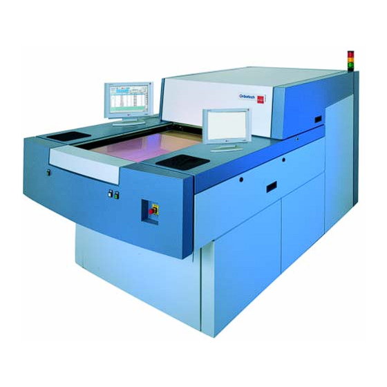
About the DP-100SL ™ The DP-100SL is a laser direct imaging system that receives PCB data from CAM workstations and plots it directly on resist-coated panels. Loading and unloading of the PCBs is done manually. The standard... - Page 8 Figure 1.1 DP-100SL Laser Direct Imaging System The DP-100SL is capable of exposing large format images on inner and outer layers, SBU and flex PCBs, printing highly accurate 2 mil lines and ¼ spaces at mil resolution. The system is compatible with the existing production processes, operating in a yellow room environment;...
-
Page 9: Intended Use
Intended Use The DP-100SL is intended for the manufacturing of printed circuit boards. It is designed to allow exposure of UV-sensitive resists, films, and similar materials typical of the circuit board industry. However, because of the numerous interrelations between substrate and laser imaging as the exposing technique, the system may only be used with such UV-sensitive materials that have been specifically approved by the manufacturer. - Page 10 Laser Safety The DP-100SL system is classified as a Class 1 laser product, in compliance with EN60825-1 standard. Laser Definition A Coherent Paladin 355-4 class 4 laser is used as main light source.
- Page 11 At the user level, the imager is a Class 1 laser device (no special protection needed) during all standard operations. However, during certain service procedures, Class 4 will be reached, and therefore a warning light must be installed (see Chapter DP-100SL Site Preparation Guide...
- Page 12 Orbotech recommends that you provide laser safety training to all employees who work on or around the laser system so that these employees understand the bio-effects of lasers and laser radiation.
-
Page 13: Caring For Your System
• Leaning, sitting, or stepping on the system is strictly forbidden. • The machine must not be used in any way other than specified in this manual or in the DP-100SL User Guide. Noise Level The system’s noise level is 70 dB (A). The noise level of the vacuum pump - installed in separate room- is 86 dB (A). -
Page 15: Dp-100Sl Physical Description
Chapter 2 DP-100SL Physical Description Configuration MAIN POWER PLANT AIR CONTROL BOX 40µ & 5µ FILTERED AIR PUMP HOSE CABLE DP-100SL LASER SUPPLY BOX Figure 2.1 DP-100SL Site The DP-100SL comprises the following main units: DP-100SL Site Preparation Guide... -
Page 16: Size And Weight
100,000 or better (US-Federal-Standard 209E). Size and Weight Table 2.1 lists weight and size information for the standard DP-100SL units. Table 2.1 Size and Weight of Standard DP-100SL Units (ready for operation) Unit Width Depth Height Weight... -
Page 17: Hose Lengths
** Measurements do not include a table on which the workstation is placed. The customer must supply this table. Sun workstation measurements are liable to change without notice. Hose Lengths Table 2.2 lists information on the size of the hose/s. Table 2.2 DP-100SL Hose Lengths Length Hose (standard Diameter supplied) -
Page 19: Facility Physical Requirements
Goggles must be worn. Service must only be performed by an Orbotech qualified engineer. The DP-100SL should be installed in a room that can be isolated to safeguard against laser hazards. These hazards can only arise during periodic maintenance and service, in specific situations (hood open and interlock neutralized). - Page 20 DIN/EN207 standard. The customer is responsible for providing safety goggles for his operators. If the DP-100SL is installed in an open space (not recommended), a method must be available to completely isolate the unit from the rest of the room during servicing procedures (example: relevant laser safety curtains).
-
Page 21: Height Requirements
Supply Laser Warning Lamp DP-100SL 24 V AC Max 500mA Relay Figure 3.1 External Warning Light Height Requirements Height of the system with the hood raised is 2689 mm (105.8"). We recommend a ceiling height of at least 2800 mm (110.2"). -
Page 22: Floor Area
Where a different height is required, a pedestal can be used in the operator area or additional steel plates can be put beneath the machine's support legs. Warning Avoid potential hazards with the pedestal by taking precautions such as skid-proof surface, easily perceivable edges, sufficient size, etc. Figures 3.2 pages 19 and 20), show system dimensions. -
Page 23: Access - Doors And Hallways
Floors, Walls, Ceilings and Furniture The floor must have sufficient strength to support the DP-100SL system, which weighs approximately 4409 lb. (2000 kg). Floor strength of 1800 Kg/m² is required, as contact areas between system legs and the floor are small. -
Page 24: Yellow Room Illumination
Ceiling—painted in the same manner as the walls, or covered with non- shedding ceiling tiles. Floors—covered with antistatic tile, rubber, or linoleum. Carpeting is not allowed. Furniture—should be resistant to static buildup. Cloth-covered seats are preferable to plastic-ones. The feet of the furniture should not be insulated from the ground, for example by rubber caps. - Page 25 Figure 3.2 System Dimensions–Front View DP-100SL Site Preparation Guide...
- Page 26 Figure 3.3 System Dimensions–Side View Chapter 3 Facility Physical Requirements...
- Page 27 Figure 3.4 Site Dimensions–Standard Conf iguration DP-100SL Site Preparation Guide...
- Page 28 11.81 in. 300 mm 3-Phase Control External Power Supply 200-400 VAC, 50-60 Hz To Vacuum Pump Control Signal (24V) From DP-100SL System Figure 3.5 Mount Description for Vacuum Control Box Chapter 3 Facility Physical Requirements...
-
Page 29: Environment & Climate
No organic chemicals or ammonia may be present in the air of the clean room. We strongly recommend to place the DP-100SL in an independent room environment (i.e. not be part of a larger room), with the following conditions: •... - Page 30 Unit 20 °C to 23 °C (68 °F to 73 °F) 0 °C to 35 °C (32 °F to 95 °F) DP-100SL * Storage temperature allowed only when in original packaging. Caution In order to achieve the specified system performance, the imager room temperature must be set within the above range, and must not fluctuate more than ±2 ºC from the set point during operational hours.
- Page 31 Table 4.2 Operating Humidity Operating Humidity Storage Humidity* Unit 50% to 60% 10% to 80%, non-condensing DP-100SL * Storage humidity allowed only when in original packaging. Heat Dissipation Table 4.3 Maximum Heat Dissipation for System Units Unit Heat Dissipation DP-100SL...
-
Page 33: Electricity
* Recommended current specifications for electrical outlet. Note • The DP-100SL machine comes with a 10m connecting cable, that must be connected to a general clamp at the rear wall close to the DP-100SL. • The transformer , when required, is located inside the DP-100SL machine. -
Page 34: Grounding
* Recommended current specifications for electrical outlet. Grounding The DP-100SL ground should be connected to a special ground line, which is connected to the building ground. A fixed installation to the ground has to be provided before switching on the system. Ground connection impedance must be <0.5 Ohms. - Page 35 Neutral to Ground (common mode) Table 5.4 Allowable Voltage Transients–Europe/Japan Transient Amplitude (Volts) Transient Duration (msec) Japan Europe <5 <55 <110 5 to 50 <25 <50 ±10% nominal ±10% nominal >50 (according to Table 5.1) (according to Table 5.1) DP-100SL Site Preparation Guide...
-
Page 36: Electrical Protection
Electrical Protection An automatic, slow-blow 3-phases circuit breaker (*) should be installed in series to the power line. Note (*) Release characteristic C in compliance with EN 60898 standard. Table 5.5 Requirements for the circuit breaker 400 V 480 V 200 V Unit (Europe) -
Page 37: Vacuum Pump
Chapter 6 Vacuum Pump The vacuum pump is provided by Orbotech with the system. All preparations required for installation, and the installation itself, are the responsibility of the customer. The vacuum pump should be installed in an isolated environment due to its noise level (86 dB (A)). - Page 38 Maximum allowed distance between system and pump is 40 m (132 ft.): DP-100SL PUMP Max. 40 m (132 ft) Figure 6.1 Vacuum pump–distance from DP-100SL Chapter 6 Vacuum Pump...
-
Page 39: Communication
Phone Lines A phone line should be installed near the system for troubleshooting and for remote instructions to operators by Orbotech personnel. The customer will supply the telephone. A second line should be available for remote diagnostics via modem. Both lines should have direct outside dialing. -
Page 41: Air
Filtered (dust: 0.1 µm, 0.1 mg/m³) Free of oil (oil: 0.01 mg/m³) 10 mm (outside diameter) Tube connectors It is the customer’s responsibility to maintain filtering of the outside supply to ensure an oil-free compressed air supply. DP-100SL Site Preparation Guide... - Page 42 Filtration and Control Compressed air must be sufficiently clean to prevent it from causing malfunction or damage. A filtration system similar to the one in Figure 8.1 is recommended. Regulator with Pressure Gage (FESTO LR-1/2-D-MIDI or equivalent) 5m filter 40m filter (FESTO LFMB-1/2-D-MIDI-A (FESTO LF-1/2-D-MIDI-A or equivalent)
-
Page 43: Shipment And Delivery
Chapter 9 Shipment and Delivery Shipping Information and Responsibility Orbotech or its agents will arrange shipment to the customer's facilities. It is the customer's responsibility to provide Orbotech with delivery instructions. The customer is responsible for transporting system units to a suitably prepared installation site, and verifying that the units can be freely moved into the installation site. -
Page 44: Equipment
• J-Bar Personnel The customer must furnish professional riggers to unload the crates and transfer them to the site. The riggers will assist Orbotech personnel in unpacking the equipment. No equipment should be unpacked before the arrival of Orbotech personnel. -
Page 45: A - Approved Materials
Approved Materials This appendix lists the UV-sensitive materials approved for use with the DP-100SL system. All specified materials have been successfully tested in laser direct imaging jobs. Nevertheless, in order to assure successful system operation, you need to set the system up according to your working environment. - Page 46 Table A.1 List of Approved Dry Film Resists Approved for Type Manufacturer UV Marker AQUAMER DI 110 Mac Dermid AQUAMER DI 115 AQUAMER DI 120 Ordyl U 430 Tokyo Ohka Ordyl U 440 Ordyl U 450 Ordyl alpha 340 Ordyl alpha 450 Photec SL 1030 Hitachi Photec SL 1040...
-
Page 47: Films
CU4 Kodak Contact 2000 Kodak CA4 Kodak Contact 2000 Kodak DC7 day-light-film Agfa Proof Materials Table A.3 List of Approved Proof Materials Type Manufacturer Dylux paper 535-1 DuPont Dylux paper 503-1 DuPont LCF (Laser Check Film) DuPont DP-100SL Site Preparation Guide... -
Page 49: B - Customer Site Preparation Checklist
Air line pressure: 0.7 ~ 1.0 MPa (7 - 10 bar) Air supply rate of 55 liters/minute ³ Quality: dry (water 0.03 g/m ³ filtered (dust: 0.1µm, 0.1 mg/m ³ free of oil (oil: 0.01 mg/m φ 10 mm tube connectors DP-100SL Site Preparation Guide... - Page 50 Maximum voltage transient of _____________ Automatic slow blow circuit breaker installed in series in each power line. DP-100SL connected to special ground line which is connected to the building ground. Ground connection impedance less than 0.5 Ohms. Electrical power for air conditioning is from different source than the system.
- Page 51 Pump Room Issues Complete Pending Date Notes Pump room size at least: 0.5 x 1 (meters) 1.64 x 3.28 (feet) Pump room is its own room with its own environment (must be ventilated!). Pump installed and connected. DP-100SL Site Preparation Guide...
- Page 52 Pump Room Issues (cont.d) Complete Pending Date Notes Control box installed and connected. Hoses routed correctly and accessible for maintenance. Imaging Room Environment Issues Complete Pending Date Notes Room temperature with machine in operation: °F ~ °F ( °C ~ °C ±2°C Room temperature with machine in original...
- Page 53 A phone line with IDD is installed near the system. A second phone line with IDD is installed for remote diagnostics via modem. Sun Workstation Issues Complete Pending Date Notes Table-top space is allocated for workstation. A 1KW UPS is recommended. DP-100SL Site Preparation Guide...
- Page 54 Table tooling hole dimensions were sent to Orbotech for OK. LDI resist passed successfully all the processing tests (including contact printing). * Depends on technology and resist Checked by: Orbotech Representative: ________________ Date: _______________ Customer Representative: ________________ Date: _______________ Appendix B Customer Site Preparation Checklist...
Need help?
Do you have a question about the DP-100SL and is the answer not in the manual?
Questions and answers