Table of Contents
Advertisement
Available languages
Available languages
Quick Links
1 ½"
2"
mm
mm
A
99,5
110
B
182
228
C
29,5
38
D
48
60
E
61,5
81
F
163,5
210
G
295
339
H
39
36
I
87,5
114
J
117
117
K
175
228
L
125
125
M
165
165
N
140
140
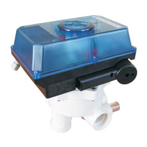
Aquastar MP-6 Pos. 1 1/2", 2", 3" 230 / 24 VAC
3"
mm
170
330
50
85,5
110
306
436
50
165
117
330
125
165
140
L
H
C
A
B
Zertifiziert nach
certified acc. to
EN ISO 9001:2000
D
GB
N
Advertisement
Chapters
Table of Contents

Summary of Contents for praher Aquastar MP-6 Series
- Page 1 Aquastar MP-6 Pos. 1 1/2”, 2”, 3” 230 / 24 VAC 1 ½“ 2“ 3“ 99,5 29,5 85,5 61,5 163,5 87,5 Zertifiziert nach certified acc. to EN ISO 9001:2000...
-
Page 2: Table Of Contents
10.3 Aquastar MP6 3” 230/24V Handnotbetätigung 11.1 Demontage 11.2 Montage SERVICE-CENTER (TEL.): Österreich ++43 / (0) 7262 / 61 178-0 austria@praher.com Deutschland ++49 / (0) 9171 / 96 77-0 germany@praher.com Spanien ++34 / 93 / 774 / 16 / 19 spain@praher.com... -
Page 3: Urheberrecht
Rechte unter Vorbehalt der Praher Kunststofftechnik GmbH. Die Bedienungsanleitung ist für die Bedienperson bestimmt. Die Vervielfältigung, Reproduktion oder Übersetzung dieser Dokumente in andere Sprachen, ganz oder teilweise, bedarf der ausdrücklichen Genehmigung durch die Praher Kunststofftechnik GmbH. © 2006 PRAHER Kunststofftechnik GmbH... -
Page 4: Arbeitssicherheitshinweise
Nichtbeachten der Hinweise in der Bedienungsanleitung bezüglich Montage, Aquastar Inbetriebnahme, Betrieb und Wartung des Aquastar Eigenmächtige bauliche Veränderungen am Mangelhafte Überwachung von Geräteteilen, die einem Verschleiß unterliegen Aquastar Unsachgemäße durchgeführte Reparaturen am Aquastar Fälle durch Fremdkörpereinwirkung und höhere Gewalt am Bei Schäden die durch Nichtbeachten der Bedienungsanleitung entstehen oder Verletzung der plombierten Teile, erlischt der Gewährleistungsanspruch. -
Page 5: Restrisiken
Zustand durchgeführt werden. 7. Allgemein PRAHER Aquastar Steuerungen sind hochwertige technische Produkte, die mit großer Genauigkeit und nach modernsten technischen Fertigungsmethoden hergestellt werden. Sollten trotzdem berechtigte Beanstandungen vorhanden sein, werden diese natürlich schnellstmöglich behoben. Für das Gerät gilt eine Gewährleistung nach geltendem EU-Recht. -
Page 6: Montage
8. Montage Geräteinstallation - Installation des Ventils: Binden sie das Ventil entsprechend der Beschriftung und der folgenden Skizze in die Rohrleitung ein. Verwenden sie Übergangsverschraubungen. Dichten sie bei Gewindeanschlüssen nur mit Teflonband ab. Das Gerät ist zwar in jeder Lage funktionsfähig, sollte jedoch nach Möglichkeit nicht mit dem Stellantrieb nach unten montiert werden. -
Page 7: Ventilsteuerung
9. Ventilsteuerung Motor S1 - Endschalter GESCHLOSSEN S2 - Endschalter FILTERN S3 - Endschalter RÜCKSPÜLEN S4 - Endschalter NACHSPÜLEN S5 - Endschalter ENTLEEREN S6 - Endschalter PUMPE S7 - Endschalter ZIRKULIEREN Motor nur bei 3" Ventil 24 / 230V AC 50/60Hz Versorgungsspannung für Filterpumpe... -
Page 8: Explosionszeichnungen
10. Explosionszeichnungen 10.1 Aquastar MP6 1 1/2” 230/24V 1. Schauglas + O-Ring 2. Deckel für Superstar 3. SK-Schraube 4. Notgriff 5. 1 1/2” Ventildeckel 6. O-Ring - Gehäuse- deckel 7. 1 1/2” Ventil 8. Platine 9. Pumpenendschalter 10. Getriebemotor 11. O-Ringe Ventilteller 12. -
Page 9: Aquastar Mp6 2" 230/24V
10.2 Aquastar MP6 2” 230/24V 1. Schauglas + O-Ring 2. Deckel für Superstar 3. SK-Schraube 4. Notgriff 5. 2” Ventildeckel 6. O-Ring Gehäuse deckel 7. 2” Ventil 8. Platine 9. Pumpenendschalter 10. Getriebemotor 11. O-Ringe - Ventilteller 12. Ventilteller 13. Moosgummischnur... -
Page 10: Aquastar Mp6 3" 230/24V
10.3 Aquastar MP6 3” 230/24V 1. Schauglas + O-Ring 2. Deckel für Superstar 3. SK-Schraube 4. Notgriff 5. 3” Ventildeckel 6. O-Ring - Gehäuse- deckel 7. 3” Ventil 8. Platine 9. Pumpenendschalter 10. Getriebemotor 11. O-Ringe - Ventilteller 12. Ventilteller 13. -
Page 11: Handnotbetätigung
11. Handnotbetätigung Einsatz bei Stromausfall oder Steuerungsproblemen 1. Vor jeder Betätigung der Handnot, Ventil von Stromkreis trennen Steuerkabel zum Ventil unterbrechen 2. Systemdruck im Ventil absenken (Pumpe abschalten, auf eventuell vorhandene Wassersäulen achten und Kugelhähne schließen) 3. Betätigung der Handnot siehe nachstehende Skizze ACHTUNG Vor jeder Handnotbetätigung ist der Systemdruck des Ventils abzusenken Die Handnotbetätigung ist nicht als Ersatz für den elektrischen Antrieb... -
Page 12: Montage
11.2 Montage... - Page 13 Emergency manual override 11.1 Dismantling 11.2 Installation SERVICE-CENTER (TEL.): Austria ++43 / (0) 7262 / 61 178-0 austria@praher.com Germany ++49 / (0) 9171 / 96 77-0 germany@praher.com Spain ++34 / 93 / 774 / 16 / 19 spain@praher.com Canada ++1 / 705 / 725-1100 canada@praher.com...
-
Page 14: Copyrights
This Operating Manual is designed to use by operating personnel. Copying, reproduction or translation of the present document into other languages in whole or in part is subject to express written permission by Praher Kunststofftechnik GmbH. © 2006 PRAHER Kunststofftechnik GmbH... -
Page 15: Instructions For Safety At Work
Non-compliance with the instruction contained in the Operation Manual fpr Aquastar installation, putting into operation, operation and maintenance of the Aquastar Unauthorized modification of the Insufficient monitoring of components subject to wear and tear Aquastar Inadequately performed repair of the Aquastar Damage of the resulting from foreign matter or Force Majeure... -
Page 16: Residual Risk
(level switch). 7. General PRAHER Aquastar controls are significant technical products, which are manufactured with high accuracy to the most modern technical production methods. Entitled complaints will natuarally be rectified as fas as possible if they occur. -
Page 17: Function And Installation
8. Assembly Device installation - installation of the valve: Install the valve in the conduit according to the labelling and the sketch below. Use adapter unions. Threaded connections should be sealed only with Teflon strip. Although the device works in any position, it should not be mounted actuator down, if possible. -
Page 18: Wiring Diagram
9. Wiring diagram engine S1 .. Limit switch CLOSED S2 .. Limit switch FILTER S3 .. Limit switch BACKWASH S4 .. Limit switch RINSE S5 .. Limit switch WASTE S6 .. Limit switch PUMP S7 .. Limit switch RECIRCULATE engine only 3"... -
Page 19: Exploded Drawing
10. Exploded drawing 10.1 Aquastar MP6 1 1/2” 230/24V 1. Inspection glas + O-Ring 2. Cover for Aquastar 3. Screw 4. Emergency grip 5. 1 1/2” valve vover 6. O-ring 7. 1 1/2” valve 8. Board 9. Pumping limit switch 10. -
Page 20: Aquastar Mp6 2" 230/24V
10.2 Aquastar MP6 2” 230/24V 1. inspection glas + O-ring 2. cover for Aquastar 3. screw 4. emergency grip 5. 2” valve cover 6. O-ring 7. 2” valve 8. board 9. pumping limit switch 10. motor 11. O-Rings 12. valve plate 13. -
Page 21: Aquastar Mp6 3" 230/24V
10.3 Aquastar MP6 3” 230/24V 1. inspection glas + O-ring 2. cover for Aquastar 3. screw 4. emergency grip 5. 3” valve cover 6. O-ring 7. 3” valve 8. board 9. pumping limit switch 10. motor 11. O-Rings 12. Valve plate 13. -
Page 22: Emergency Manual Override
11. Emergency manual override Operating with power failure or control system problems 1. Before any use of the hand emergency, seperate valve from the electric circuit - interrupt control cables to the valve. 2. Lower system pressure in the valve (switch pump off, take care of possibly existing water pillars and close ball valve). -
Page 23: Installation
11.2 Installation...
Need help?
Do you have a question about the Aquastar MP-6 Series and is the answer not in the manual?
Questions and answers