
Summary of Contents for Rioned Profijet Tier4 STAGE III B
- Page 1 USER’S MANUAL RIONED TIER4 / STAGE III B ENGINE RIONED P.O. Box 5070 5004 EB Tilburg The Netherlands Telephone :+31 13 5479100 Telefax : +31 13 5479104...
- Page 2 RIONED. This restriction also holds for the corresponding drawings and diagrams. RIONED has the right to change parts at any time without any prior or direct warning to the client. Also, the contents of this manual can be changed without any prior warn- ing.
- Page 3 Foreword This user’s manual is a manual for the professional user. This user’s manual has the purpose to control the machine in a safety manner and must be saved with the machine. The photos and drawings help you understand the text easier. First the user’s manual gives you an overview of the most important safety aspects.
- Page 4 01/17...
-
Page 5: Table Of Contents
Table of Contents Introduction ................9 Use.................. 9 Security ..................11 Instruction indications in this manual........11 Descriptions security measures.......... 11 Personnel protection outfit ..........11 Personnel qualification and education ......... 11 Danger that can occur if the security regulations aren’t observed Working safely .............. - Page 6 Symbols ................... 41 Fuel tank ................ 41 Frame ................41 Pressure gauge..............41 Security sticker ............... 42 Options..................43 Second HP-hose .............. 43 Pulsator system ............... 43 Anti-freeze with anti freeze tank ........43 Water level control............44 Working lamp..............45 Suction Ventury...............
- Page 7 15.10 Run Dry................81 15.11 Water Level Maximum ............82 15.12 Service Interval ............... 82 Index ..................83 01/17...
- Page 8 01/17...
-
Page 9: Introduction
INTRODUCTION RIONED wishes to thank you for your purchase of the RIONED drain and sewer- clearing machine. We recommend that you read this manual thoroughly and see that the machine is handled and maintained in the proper manner. If your machine should give trouble and need servicing, when you want to order parts, or if you have any questions, contact your RIONED dealer. - Page 10 01/17...
-
Page 11: Security
SECURITY Be responsible for other people when you are working with this machine. This manual contains instructions for fundamental conditions that must be followed by use and maintenance of this machine. That is why it is necessary that authorised and qualified personnel must read the user's manual and the user’s manual must always be available with the machine. -
Page 12: Danger That Can Occur If The Security Regulations Aren't Observed
Changes to the machine are only permitted if Rioned has given written authorisation. The use of original spare parts and accessories are for the safety necessary. Rioned is not responsible for injuries or damages if other spare parts are used. -
Page 13: Improper Use
2.10 Improper use The security during working with the machine is only guaranteed if the use of the machine is conform the user’s manual. The limits that are written in chapter “Technical Specifications” and “Appendix” may never be overstepped. If the machine does not work or give troubles, it is forbidden to work further with the machine. - Page 14 01/17...
-
Page 15: Technical Specifications
TECHNICAL SPECIFICATIONS General Description (symbol) Unit Dimensions see chapter 14.3 Dimensions 2 x 300l water tank page: 73 Quantity standard water tank : 300 l a piece Fill medium : Water Maximum temperature medium : 55 °C (333,15 K) Total length high-pressure hose / diameter : 160 m / ½” (NW13) Total length supply hose / diameter : 35 m / ¾”... - Page 16 01/17...
-
Page 17: Construction
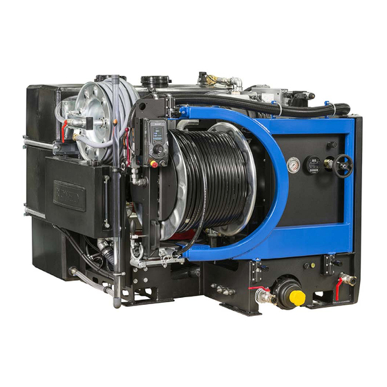
CONSTRUCTION The high-pressure machine contains the following main parts: High-pressure hose on reel Supply hose on real Valve supply hose Control box Hose holder Hose guide High-pressure (HP) valve Supply pipe Water filter Drain valve Pressure regulator Pressure gauge Hydraulic reel control Swivel locking device (3x) Reel locking device Valve water filter... - Page 18 01/17...
- Page 19 01/17...
- Page 20 01/17...
-
Page 21: Econtrolplus
eControlPlus 5.1 Control box: Corona Navigation bullets Function Tachometer Pointer ECO Mode Icons Left Icons Right Engine LED Engine symbol High Pressure LED High Pressure symbol Vacuum LED Vacuum symbol Navigator Emergency Stop Key (Off-Manual-Riomote) 01/17... - Page 22 01/17...
-
Page 23: Explanation Graphics (Only Econtrolplus)
Explanation Graphics (only eControlPlus) 01/17... -
Page 24: Corona
6.1 Corona The Corona is OFF (grey) unless: • The Control Unit is: Set to Riomote Control Error applicable Switched OFF by the Eco Start/ Stop-system Diesel engine: Pre Heat, Petrol engine: no function Run dry error Oil level 01/17... -
Page 25: Push Buttons
6.2 Push buttons When system is switched ON with the key (42), are lighted. is lighted on machines featuring a vacuum functionality. are lighted when the corresponding functionality is active, regardless Manual Control or Riomote Control. In case of “Run Dry”, is blinking with 1 ON/OFF cycle per second. - Page 26 01/17...
-
Page 27: Navigation Bullets
6.3 Navigation bullets The navigation bullet (27) has two general states: • Passive (Grey) • Active (Blue) Depending on the user’s location in the menu, one of them is on display or, in case of a pop-up, all navigation bullets disappear. Features in navigation bullets are in specified order, if applicable: •... -
Page 28: Function
6.4 Function A function (28) has two general states: • Passive (Grey) • Active (Blue) Depending on the user’s location in the menu, one of them is on display or, in case of a pop-up, all navigation bullets disappear. Regardless if a function is active, possible settings on display should always in- dicate its current status. -
Page 29: Tachometer
6.5 Tachometer The tachometer (29) has two general states: • Passive (default) • Passive (eco) • Active (default) • Active (eco) Depending on the user’s location in the menu, one of them is on display. The pointer which indicates the engine’s RPM should always display the current RPM. -
Page 30: Icons
6.6 Icons The icons always display the current status of the corresponding feature, regardless “Manual Control” or “Riomote Control”. Since the “Hose Reel” and “Spray Bar” are never used simultaneously, they share the same designated area on screen. • Pulsator on •... -
Page 31: Control
CONTROL If you control, maintain or inspect the machine, you must have the right qualifications for this job. If you do not have the necessarily knowledge, you may not use the machine. Further, you must convince yourself that you understand this manual thoroughly. -
Page 32: Hose Guide
Reel locked Unwind the hose Reel “out of gear” Hose guide Purpose: To guide the HP hose into the sewer. To wind the HP hose on the reel drum. To keep the hose clean. Use: • Put the end of the hose through the opening of the hose guide. •... -
Page 33: Starting The Engine
By the supply hose. Couple the supply hose (2) onto a water tap an open the water tap an the supply valve. Through the supply pipe (8). Connect a supply hose to the supply pipe. Open the water tap and supply valve. -
Page 34: Starting The Engine At The Back Of The Unit
Put on protection looking glasses and ear protectors before starting the machine. Start the machine. Proceed as follows: Starting the engine at the back of the unit: Position key control box: • Insert key: • Position 1 (manual control): • Position 2 (remote control): 7.7.1 Start engine manually: Put the key into the keyhole. - Page 35 • “Work safe” is displayed for 2 seconds. • Icon “Manual control ON” is displayed for 2 seconds. • Then the main menu is displayed • ECO mode is standard always active if option “ECO Start/ Stop” or “ECO Stop” is available. Check the error icon.
-
Page 36: Unclogging A Drain
Let the engine warm up. After 3 minutes the machine is ready for use. Unclogging a drain Screw a suitable nozzle onto the high-pressure hose. Put the hose through the hose guide (6) for safety manners. Unwind the hose a little. Put the nozzle into the drain that is to be cleaned. - Page 37 The hose will now unwind and work its way into the drain. Check that the water drains away. When the blockage has been cleared, continue to flush for a while. At the same time wind the hose up slowly. Important! Rewind hose onto reel under pressure to avoid crushing.
-
Page 38: Cleaning A Wall, Terrace Or Floor
Attention! Ensure that the spraying nozzle does not leave the drain! Water under high-pressure may cause severe injuries! Cleaning a wall, terrace or floor. Caution! Before using a spray gun, you must always set the pressure below the maximum (±the half of the maximum pressure). You must do this before you start the machine. -
Page 39: Stop Working
adjusted pressure can be read from the pressure gauge (12) on the machine when the spray gun is open. Pull the trigger of the spray gun. Stop spraying Release the trigger of the spray gun. 7.10 Stop working HP pump off and throttle down: Press button “Stop spraying”... -
Page 40: Additional Preparations When Preparing For Use
7.12 Additional preparations when preparing for use: Turn on the machine and let the high-pressure pump drain all anti- freeze into the anti-freeze tank. The antifreeze can be reused. Ensure that no water is mixed with the antifreeze. If too much water gets into the antifreeze, it is not suitable for re-use. -
Page 41: Symbols
SYMBOLS Fuel tank Ultra Low Diesel Sulfur Frame Switch to regenerate the Engine Pressure gauge Maximum allowed pressure Danger zone Working area 01/17... -
Page 42: Security Sticker
Security sticker 01/17... -
Page 43: Options
OPTIONS Second HP-hose Purpose: Most used in smaller sewers/pipes or with spray-gun. Position: The second hose reel can be mounted at the machine instead of the supply reel hose. Total length 2e high-pressure hose can differ from, 50 m and higher. Pulsator system Purpose: With less water use, quicker to the stoppage. -
Page 44: Water Level Control
Open the antifreeze valve. Press the overrun button and start the engine. Check if the HP-valve on the machine is open. Push button HP ON on the control box. Let the high-pressure pump remove all the water, which is still in the high-pressure hose and pump. -
Page 45: Working Lamp
• Depressurize the supply pipe. Press the button. • Uncouple the supply hose. Working lamp Control: By means of switch you can turn the working lamp ON and OFF. Suction Ventury Use: The suction ventury takes care that you can pump dirt and/or liquid out of reservoirs. - Page 46 • Switch on the high-pressure pump, if necessary. • Open the HP valve (7). Stop suction: • Close the handle of the high-pressure valve. • Stop the machine. Uncouple the HP hose. 01/17...
-
Page 47: Options Econtrol
Options eControl 01/17... -
Page 48: Eco Mode Off
10.1 ECO mode OFF To change the ECO mode, the engine must run! ECO mode is standard always ON if function is available on machine. Turn the Navigator (40) clockwise and set the navigation bullet to position 5 “Eco Mode”. Push the Navigator to activate the function. - Page 49 • “Eco Mode” icon extinguishes • Navigation bullet lightens blue • “Eco Mode” icon disappears Wait 2 seconds! • “Hours Total” is displayed. 01/17...
-
Page 50: Eco Versions
10.2 ECO versions The ECO mode has two versions: ECO Start/Stop ECO Stop 10.2.1 ECO Start/Stop behaviour: Stop: • Press “High pressure OFF”: Water stops spraying RPM engine decreases. Engine stops after 30 seconds if no activity takes place. Start: •... -
Page 51: Riomote Control
10.3 Riomote Control Purpose: To operate the high-pressure machine from a distance. 10.3.1 Emergency stop test Check before working with the Riomote Control if the emergency stop works well. Proceed as follows: Put the key into the keyhole. Turn the key to position 2 “Radio Control ON”. •... - Page 52 • Start the engine by means of button “START” • Push the “STOP” button The machine has to cut off now. If this is not the case it is not allowed to work with the Riomote Control. Contact your supplier. 10.3.2 Battery If the indication on the Riomote Control starts burning it's indicates...
- Page 53 10.3.3 Functions 5 channel Riomote Control: Throttle down Throttle up Stop spraying Start spraying Emergency stop 10.3.4 Functions 7 channel Riomote Control: Throttle down Throttle up Stop spraying Start spraying Stop the engine Start the engine Emergency stop 10.3.5 Functions 9 channel Riomote Control: Throttle down Throttle up Stop spraying...
- Page 54 10.3.6 Functions 11 channel Riomote Control: Throttle down Throttle up Stop spraying Start spraying Stop the engine Start the engine Wind the HP hose Unwind the HP hose Emergency stop Pulsator on Pulsator off 10.3.7 Functions 13 channel Riomote Control: Throttle down Throttle up Stop spraying...
-
Page 55: Management
10.4 Management Turn the Navigator (40) clockwise and set the navigation bullet to position 6 “Management”. Push the Navigator to activate the function. • Navigation bullet extinguishes. • Management underline lightens. Software version. • Press Navigator shows actual software settings •... - Page 56 01/17...
-
Page 57: Maintenance
MAINTENANCE Attention! Always stop the engine first and depressurize the system before serving or repairing the machine. To depressurize the system, you open the HP valve. If the spray lance gun is attached you must also pull the trigger. 11.1 Daily maintenance Oil level Check all oil levels once a week. -
Page 58: Hydraulic System
Important! You have to renew the hydraulic oil at least ones a year! Only use oil HESTIA 46. Order number Rioned 71-003-500-046 Check, every time before use, if the level of the oil is sufficient. Proceed as follows: Stop the machine. -
Page 59: Engine Control Module
ECM delivered with this machine. 11.6 Extensive periodical maintenance Have the high-pressure machine checked and maintained from time to time by the technical service of Rioned. In this way, long life and quality will be guaranteed. 11.7 Maintenance scheme Interval... - Page 60 Cleaning carriage weekly or with strong pollution. Service engine Every 250 working hours or at least once every six month Lubricate moving parts Every 250 working hours or at least once every six month Cleaning pressure regulator Every 250 working hours or at least once every six month Renew pump oil Every 250 working hours or once a year...
-
Page 61: Troubleshooting
TROUBLESHOOTING Failure Reason Solution Engine does not start or stops Machine has run out of fuel Add fuel abruptly. Main or secondary fuse blown Replace the defect fuse and restart engine. If problem repeats, contact your dealer Battery voltage too low. Load or replace. - Page 62 Failure Reason Solution Pressure varies. Water level in tank too low Stop the engine, refill the tank and restart engine Water supply valve not sufficiently Open the supply valve completely opened Water filter clogged. Stop the machine and clean the filter Pump sucks air Stop the machine and check all hoses and couplings for leakage...
- Page 63 Failure Reason Solution Certain functions are not exe- Receiver is faulty Contact your supplier cuted Interruption in electric circuit Check all plugs. Plug in and push. Check control lights if functions are indicated 01/17...
- Page 64 01/17...
-
Page 65: Exploded Views And Part Lists
EXPLODED VIEWS AND PART LISTS 01/17... -
Page 66: Exploded View Pump P55(80L-280B)
13.1 Exploded view Pump P55(80L-280B). D1763 0709S 01/17... -
Page 67: Part List Pump P55(80L-280B)
13.2 Part list Pump P55(80L-280B). Ersatzteilverzeichnis P55/80-250G Best.-Nr.: 00.5935 Spare Parts List Code Nr. Lfd. Nr. Stückzahl Best.-Nr. Benennung Description Item No. No. Off Code No. 01.0709 Antriebsgehäuse Crankcase 00.2914 Ölauffüllstopfen kpl. Oil Filler Plug Assy 00.2416 Ölschauglas Oil Sight Glas 03.0266 Getriebedeckel Crankcase Cover... -
Page 68: Pressure Regulator Ulh 262-2H
13.3 Pressure regulator ULH 262-2H 01/17... -
Page 69: Water Filter
13.4 Water filter Order number: 39450500688 01/17... - Page 70 01/17...
-
Page 71: Appendix
14.1 EC declaration Of Conformity For Machinery RIOR B.V. / RIONED Centaurusweg 45, Tilburg, The Netherlands, Herewith declares that: High pressure device RIONED ProfiJet, Machine number: • is in compliance with the Machinery Directive (2006/42/EC); • is in conformity with the provisions of the following other EEC direc-... -
Page 72: Sales Managers
5015 TC Tilburg Tel.: +31 13-547 91 00 Hans de Laat Tel. 06-54973081 Area Sales Manager Centaurusweg 45 5015 TC Tilburg Tel.: +31 13-547 91 00 REPAIR THE NETHERLANDS Rioned Centaurusweg 45 5015 TC Tilburg Tel.: +31 13-547 91 00 01/17... -
Page 73: Dimensions 2 X 300L Water Tank
14.3 Dimensions 2 x 300l water tank 01/17... -
Page 74: Dimensions 2 X 400L Water Tank
14.4 Dimensions 2 x 400l water tank 01/17... - Page 75 01/17...
- Page 76 01/17...
-
Page 77: Errors Econtrol
Errors eControl 15.1 Emergency stop A pop-up notifies the user that Emergency Stop is pushed. Engine, High Pressure, Vacuum, Pulsator, Hose Reel and/or Spray Bar are switched OFF. Eco Mode is switched ON. The user can only restart operation by releasing (rotate) the Emergency Stop. 15.2 Temperature engine A pop-up notifies the user of the error. -
Page 78: Temperature Transmission
15.3 Temperature Transmission A pop-up notifies the user of the error. Whilst applicable, the error is also listed under “Management” (see chapter 10.4 "Management" page.: 55). Engine, High Pressure, Vacuum, Pulsator, Hose Reel and/or Spray Bar are switched OFF. Eco Mode remains unchanged. The user can dismiss the pop-up by pushing the Navigator in Manual Control. -
Page 79: Temperature Heat Exchange
15.5 Temperature Heat Exchange A pop-up notifies the user of the error. Whilst applicable, the error is also listed under “Management” (see chapter 10.4 "Management" page.: 55). Engine, High Pressure, Vacuum, Pulsator, Hose Reel and/or Spray Bar are switched OFF. Eco Mode remains unchanged. The user can dismiss the pop-up by pushing the Navigator in Manual Control. -
Page 80: Oil Level
15.7 Oil level A pop-up notifies the user of the error. Whilst applicable, the error is also listed under “Management” (see chapter 10.4 "Management" page.: 55). If running, Engine to stationary. High Pressure, Vacuum, Pulsator, Hose Reel and/or Spray Bar are switched OFF. Eco Mode remains unchanged. -
Page 81: Battery Charge
15.9 Battery Charge A pop-up notifies the user of the error. Whilst applicable, the error is also listed under “Management” (see chapter 10.4 "Management" page.: 55). Engine, High Pressure, Vacuum, Pulsator, Hose Reel, Spray Bar and/or Eco Mode remain unchanged. The user can dismiss the pop-up by pushing the Navigator in Manual Control. -
Page 82: Water Level Maximum
15.11 Water Level Maximum Only available if option “Electronic Water Level control” is mounted. A pop-up notifies the user of the warning. Whilst applicable, the error is also listed under “Management” (see chapter 10.4 "Management" page.: 55). Engine, High Pressure, Vacuum, Pulsator, Hose Reel, Spray Bar and/or Eco Mode remain unchanged. -
Page 83: Index
........ 13 general security signs ..11 gloves ......11 accessories ....12 responsible ....11 antifreeze ....39 rioned ....2 attention ...... 38 icon “manual control on” . 35 injuries ......12 sales managers ....72 caution ......38 security covers .... - Page 84 01/17...
- Page 85 Product Manual Engine Control Module Kubota Diesel Engines Part Number: MVP-235 Revision: 1.2 Engine Type: Kubota Diesel with DPF Emissions Control...
- Page 86 TABLE OF CONTENTS INSTALLATION INFORMATION ……...………………………………...……………………………………………………………..CONNECTOR INFORMATION ……...………………………………...………………..…………………………………………………. MENU NAVIGATION ………………………………………………………………..……………………………………………..…………….…..MENU SYSTEM …………………………………………………………………...…………………………………………………..……………….…..OPERATOR MENU …………………………………………………………………..…………………………………………………..………….…..EMISSIONS PARAMETERS ACTIVE FAULT CODES STORED FAULT CODES OPERATION EVENT LOG ALARM EVENT LOG ENGINE PARAMETERS ENGINE IDENTIFICATION MODULE INFORMATION CONTROLER SETUP MENU ……………………………………………………………………………………………….….…………...……..
-
Page 87: Installation Information
INSTALLATION INFORMATION - 2 -... - Page 88 CONNECTOR INFORMATION BATTERY + 5VDC SUPPLY CAN HIGH NEUTRAL SWITCH CAN LOW ANALOG APS 2 DIGITAL INPUT 1 ANALOG APS 1 FUEL LEVEL PARKING BRAKE SW BATTERY - GROUND (B-) Part# 3FK-108 Connector A Kit (1) Deutsch DT06-6S plug with (6) 0462-209-10614 sockets - 3 -...
-
Page 89: Menu Navigation
MENU NAVIGATION To access the control module menu system, power the unit and press the Menu button. While pressing the menu button a message will appear to also press Enter to access. Once you have accessed the menu system, the four key pad will be used for menu navigation and therefore not available for engine speed control if the engine is running. -
Page 90: Menu System
MENU SYSTEM Operator First Menu Menu Controller Setup Menu - 5 -... -
Page 91: Operator Menu
OPERATOR MENU Emissions Parameters This menu allows for the viewing of the engine emissions data as broadcast by the ECU by pressing the up arrow button. This data includes: DOC Inlet Temperature DPF Soot Load DPF Inlet Temperature ... -
Page 92: Engine Identification
Up arrow key. The next screen will ask for a password. (ask Rioned) If no password, or an incorrect password is used, navigation into the menu is still possible and permitted, however, the ability to make changes will be restricted. - Page 93 Navigating the Controller Setup menu structure is done in the same manner as the Operator menu system. Menu will index to the next topic, The Up arrow will access the topic, etc. To make changes to the settings, you will need to locate the item you are looking to modify under the appropriate topic and then press the Enter key and the editing brackets will appear allowing you to make changes to the value or change the selection.
-
Page 94: Controler Setup Menu
CONTROLLER SETUP MENUS PARAMETER CONFIGURATION The Parameter Configuration menu allows you to configure each critical engine parameter to the source of the information. Sender type, scale and input channel to the module can be selected here. You will first select the parameter, then the properties associated with each one. Heading Default Range... -
Page 95: Throttle Configuration
THROTTLE CONFIGURATION The Throttle Configuration menu allows you to design the appropriate speed control for your application. The most common throttle control is TSC Vernier. This option allows you to start the engine at the minimum speed and control the throttle up to the maximum speed with the ability to stop anywhere in between. -
Page 96: Engine Safety Configuration
ENGINE SAFETY CONFIGURATION The Engine Safety Configuration menu enables the user to set warnings for the critical engine parameters. Care should be taken when configuring to match the engine manufacturers recommended guidelines. Heading Default Range Sender Check Bypass 0:10 Seconds 0:05 -1:00 Oil Pressure Check Off/Always/Run... -
Page 97: Module Configuration
MODULE CONFIGURATION The Module Configuration menu is available to change the behavior of the control and clear several of the log files. Heading Default Range Pressure & Temperature Units English English/Metric Pre Alarms Displayed Clear Operation Log Yes/No Clear Alarm Log Yes/No Clear Number of Starts Yes/No... -
Page 98: Panel Engine Safety Protection
PANEL ENGINE SAFETY PROTECTIONS PREALARMS AND ALARM The primary engine protection in an engine equipped with an ECU is managed by the engine’s ECU. The display will show lamp status and trouble code information based on the ECUs messaging to the display. -
Page 99: Indicator Lamps
The control panel also has the ability to monitor the engine vitals if configured. The ability to set pre alarms and alarms in the panel is supported to back up the ECUs safeties in the event the ECU shutdowns were not enabled for some reason or a more conservative setting is desired. If the parameter falls outside of the normal operating range, the control panel will stop the engine by removing power to the fuel solenoid or ignition circuit. -
Page 100: Emissions Monitoring - Regeneration
EMISSIONS MONITORING - REGENERATION The engine ECU continuously monitors the engine’s emissions parameters. When certain conditions are reached, the ECU will indicate that a regen is needed. This controller works in cooperation with the ECU to display this information as well as provide an interface between the operator and ECU. The information can be obtained by entering the Emissions Parameters menu (described above). - Page 101 Module Regen Buttons The MVP module has two regeneration function buttons, Regen Request and Regen Inhibit. Regen Request – This button will operate when a required regen has been annunciated by the ECU and subsequently denied by the Operator. The module will repost the ECU regen request every 2 minutes, however, if at any time prior to the prompt, the operator wishes to reinstitute the regen prompt, it can be done by pressing this button for at least two seconds.
- Page 102 If the operator chooses No, then the Parked Regen Needed will continue to scroll with the normal operating screen. The prompt will automatically reappear after two minutes. If the Operator chooses Yes, the controller will alert the Operator that the engine RPM may increase. This is to allow for any application that may be affected by increased RPM.
- Page 103 To ensure that the engine load is removed, the regen process requires that the parking brake input (Pin B5 - closed to ground) and the Neutral Switch (Pin B2 – closed to ground) are applied. It is not acceptable to initiate the parked regeneration when the engine load is applied. A prompt will appear for each state, with the operator pressing Enter to confirm.
- Page 104 Regen Fail / Abort The regen process will be aborted if either the Neutral Switch or the Parking Brake circuits open during the process. When this occurs, a message will appear requiring the operator’s acknowledgement. The condition causing the abort will need to be rectified and the regen process reinstated from the beginning.
Need help?
Do you have a question about the Profijet Tier4 STAGE III B and is the answer not in the manual?
Questions and answers