Table of Contents
Advertisement
Available languages
Available languages
Quick Links
Advertisement
Table of Contents

Summary of Contents for Audiotec Fischer HELIX SDMI25
- Page 1 SDMI 25 Smart Digital MOST Interface...
-
Page 2: Herzlichen Glückwunsch
Verarbeitung und eine überzeugende Anwendung ausgereifter Technologien aus. Viel Freude an diesem Produkt wünscht Ihnen das Team von AUDIOTEC FISCHER Garantiehinweis Die Garantieleistung entspricht der gesetzlichen Regelung. Von der Garantieleistung ausgeschlossen sind Defekte und Schäden, die durch Überlastung oder unsachgemäße Behandlung entstanden sind. -
Page 3: Allgemeine Hinweise
Allgemeine Hinweise Um alle Möglichkeiten des Produktes optimal ausschöpfen zu können, lesen Sie bitte sorgfältig die nachfolgenden Installationshinweise. Wir garantieren, dass jedes Gerät vor Versand auf seinen einwandfreien Zustand überprüft wurde. Vor Beginn der Installation unterbrechen Sie den Minusanschluss der Autobatterie. Wir empfehlen, die Installation von einem Einbauspe- zialisten vornehmen zu lassen, da der Nachweis eines fachgerechten Einbaus und Anschlusses des Gerätes Voraussetzung für die Garan- tieleistungen sind. -
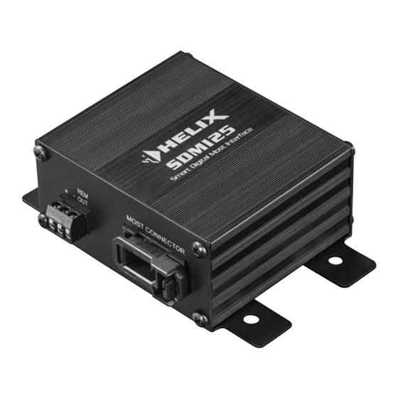
Page 4: Anschluss- Und Bedienelemente
Anschluss- und Bedienelemente Power Input Zum Anschluss an die Bordnetzspannung mit einem zusätzlichen Remote-Ausgang. Der Remote-Ausgang muss zum Ein- und Ausschalten weiterer Komponenten angeschlossen werden. MOST Connector Zum Anschluss der MOST Lichtleiterverbindung des Fahrzeugs. Optical Out Optischer, digitaler Stereo-Signalausgang im SPDIF-Format. Jumper Zur fahrzeugspezifischen Konfiguration des SDMI25. - Page 5 Inbetriebnahme und Funktionen 1 Power Input Diese Buchse dient zum Anschluss des SDMI25 an die Stromversor- gung des Fahrzeuges sowie für den Remote-Ausgang. +: Anschluss für das +12 V Versorgungskabel. Das Kabel ist am Pluspol der Spannungsquelle anzuschließen. Die Plusleitung sollte in einem Ab- stand von max.
-
Page 6: Optical Out
Inbetriebnahme und Funktionen 3 Optical Out Optischer, digitaler Stereo-Signalausgang im SPDIF-Format für den Anschluss eines Signalprozessors (DSP) oder DSP-Verstärkers. Der Ausgang hat eine „Sampling Rate“ von 48 kHz / 24 Bit und liefert ein lautstärkegeregeltes Signal. Hinweis: Dieser Ausgang liefert ausschließlich ein Stereosignal. Fader Informationen und Mehrkanal-Surroundsound-Formate wie Dolby oder DTS werden nicht unterstützt! 4 Jumper... - Page 7 Übersicht Jumper-Konfigurationen Hersteller Info Jumper Hersteller Info Jumper Seriennummer-Kopiervorgang Lamborghini mit OEM-Verstärker Audi MMI 2G, MMI 3G Mercedes NTG1 ohne AGW, NTG2 MMI 3G+ NTG2.5, NTG4, NTG4.5 MMI 3G+ NTG1 mit externer AGW E-, F-, G-Serie NTG3, NTG3.5 mit AGW (Becker) System-Signalton- Porsche bis 2008 PCM2.0,...
- Page 8 Einbau und Installation Standard Anwendungsfall. Der SDMI25 ersetzt den OEM-Verstärker OEM-Modul IN OUT Autoradio OEM-Modul SPDIF SDMI25 OEM-Verstärker...
- Page 9 Standardmäßig wird der SDMI25 wie nachfolgend beschrieben an den MOST-Bus angeschlossen. Achtung: Bei einigen Fahrzeugtypen muss der Einbau nach einem ge- sonderten Ablauf erfolgen. Informationen dazu finden Sie auf Seite 11. 1. SDMI25 Jumper auf gewünschtes Fahrzeug einstellen (siehe Seite 7). 2.
- Page 10 Einbau und Installation 4. Lichtleiterkabel MOST-Stecker-Gehäuse einstecken (Abb. 4.2). IN & OUT des Signals muss zwingend beachtet werden. Siehe hierzu Abbildung 4.1. Achtung: Vor der ersten Installation muss der Schutz der Photodio- de im MOST-Connector des SDMI25 entfernt werden (Siehe rote Markierung in Abbildung 4.1).
- Page 11 Besondere Einbauhinweise Volvo / Land Rover / Range Rover mit Komponentenschutz durch Seriennummerabfrage: OEM-Modul IN OUT Kopiert Seriennummer Autoradio OEM-Modul SDMI25 OEM-Verstärker Bevor Sie den OEM-Verstärker ausbauen, muss zuerst dessen Serien- nummer in den SDMI25 kopiert werden. Dazu gehen Sie wie folgt vor: 1.
- Page 12 Besondere Einbauhinweise 3. System einschalten. Während des Systemstarts wird die Seriennum- mer des OEM-Verstärkers automatisch in den Speicher des SDMI25 kopiert. 4. Signalquelle wechseln. Wird kein Audiosignal mehr wiedergegeben, wurde die Seriennummer erfolgreich in den SDMI25 kopiert. 5. System ausschalten. Das Y-Lichtleiterkabel und den OEM-Verstär- ker aus dem MOST-Bus ausbauen.
-
Page 13: Warranty Disclaimer
For further processing of the stereo signal a DSP (digital signal proces- sor) or DSP amplifier with optical digital input will be required. The HELIX SDMI25 highlights best quality, excellent manufacturing and state-of-the-art technology. We wish you many hours of enjoyment with your new HELIX MOST converter. -
Page 14: General Instructions
HELIX dealer. The HELIX SDMI25 may only be installed in vehicles which have a 12 Volts negative terminal connected to the chassis ground. Any other system could cause damage to the device and the electrical system of the vehicle. - Page 15 Connectors and control units Power Input Connector for the DC power supply with an additional remote output. The remote output must be used to switch on external components. MOST Connector For connecting the MOST fibre-optic cable of the vehicle. Optical Out Optical, digital stereo signal output in SPDIF format.
- Page 16 Initial start-up and functions 1 Power Input This input is used for connecting the SDMI25 to the power supply of the vehicle and for remote out. +: Connector for the +12 V power cable. Connect cable to the positive terminal of the power source. The positive cable from the power source should be provided with a main fuse at a distance of max.
-
Page 17: Technical Data
3 Optical Out Optical, digital stereo signal output in SPDIF format for connecting sig- nal processors or amplifiers with DSP. The output provides a volume controlled signal and has a sampling rate of 48 kHz / 24 Bit. Note: This output solely provides a stereo signal. Multi-channel sur- round sound formats such as Dolby or DTS are not supported! 4 Jumper These jumpers must be used to configure the SDMI25 to the individual... - Page 18 General jumper configuration map Car make Info Jumper Car make Info Jumper Serial number copy process Lamborghini with OEM amplifier Audi MMI 2G, MMI 3G Mercedes NTG1 without AGW, NTG2 MMI 3G+ NTG2.5, NTG4, NTG4.5 MMI 3G+ NTG1 with external AGW E, F, G series NTG3, NTG3.5 with AGW (Becker)
-
Page 19: Installation
Installation Default application. The SDMI25 replaces the OEM amplifier OEM module IN OUT Head unit OEM module SDMI25 OEM amplifier... - Page 20 Installation By default, the SDMI25 is connected to the MOST bus as described below. Attention: Depending on the car model, the installation must be carried out according to a special procedure. Further information can be found on page 23. 1. Adjust the SDMI25 jumpers to the appropriate car model (see page 18).
- Page 21 4. Plug the fibre-optic cable into the MOST connector housing (Fig. .2). It is mandatory to observe the direction (IN & OUT) of the optical signal. See figure 4.1. Attention: The protection of the photodiode in the SDMI25 MOST Connector must be removed before the first installation (see red marking in figure 4.1).
-
Page 22: Special Installation Instructions
Special installation instructions Volvo / Land Rover / Range Rover with component protection by serial number query: OEM module IN OUT copies serial number Head unit OEM module SDMI25 OEM amplifier Before removing the OEM amplifier, first its serial number must be cop- ied into the SDMI25, proceed as follows: 1. - Page 23 3. Switch on the system. During system start up, the serial number of the OEM amplifier is automatically copied into the memory of the SDMI25. 4. Change the signal source. If no audio signal is played back, the serial number has been successfully copied to the SDMI25. 5.
- Page 24 Audiotec Fischer GmbH Hünegräben 26 · 57392 Schmallenberg · Germany Tel.: +49 2972 9788 0 · Fax: +49 2972 9788 88 E-mail: helix@audiotec-fischer.com · Internet: www.audiotec-fischer.com...
Need help?
Do you have a question about the HELIX SDMI25 and is the answer not in the manual?
Questions and answers