
Summary of Contents for skeletal dynamics DISTAL ELBOW SET
- Page 1 SURGICAL TECHNIQUE GUIDE DISTAL ELBOW SET p r o x i m a l u l n a p l a t e As described by: Jorge L. Orbay, M.D. Miami Hand & Upper Extremity Institute Miami, Florida...
- Page 2 DISTAL ELBOW SET p r o x i m a l u l n a p l a t e Indications for Use The proximal ulna plates are intended for fixation of fractures, fusions, osteotomies and non unions of the ulna, particulary in osteopenic bone.
- Page 3 SUPERFICIAL EXPOSURE With the elbow flexed 90 make a posterior incision extending distally, curving around the olecranon and over the subcutaneous border of the ulna. NOTE: The incision can be curved slightly lateral or medial to the tip of the olecranon based on your preferred method.
- Page 4 DEEP EXPOSURE Expose the proximal ulna sub-periosteally. ACCESSING THE JOINT For olecranon fractures, enter the joint through the fracture plane by releasing the capsular attachments on the proximal fragment as needed. The articular surfaces can be evaluated at this time.
- Page 5 DEBRIDING THE FRACTURE Debride the fracture site. NOTE: It is necessary to remove callus, clot and fibrous tissue in order to achieve a proper reduction. DISTAL TRICEPS RELEASE Starting distal to proximal, split the triceps insertion longitudinally for approximately 1 cm. Elevate the triceps along a narrow longitudinal strip to provide space for the “Home...
- Page 6 PLATE SELECTION Select the appropriate length of plate that provides at least six cortices of fixation distal to the fracture line. NOTE: The shaft of the 151mm length plate can be bent using the Bending Irons. If plate bending is necessary, please refer to step 29 in this surgical technique guide.
- Page 7 FRACTURE REDUCTION Reduce the fracture by levering the shaft of the plate to the distal fragment. Confirm fracture reduction and plate alignment using fluoroscopy. Using the 2.7mm x 40mm bit, drill bicortical through the distal end of an oblong hole that is distal to the fracture line.
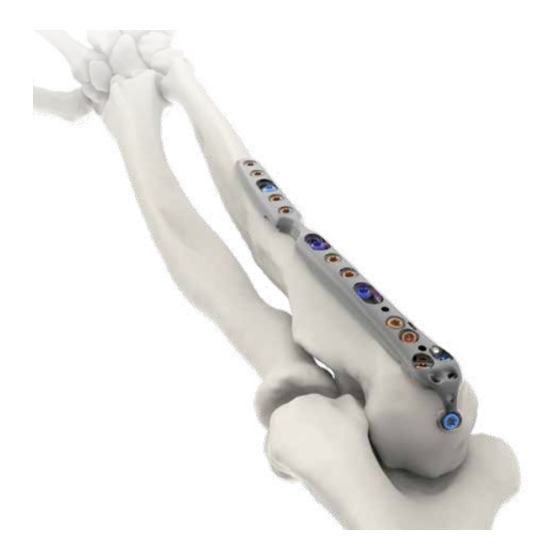
- Page 8 PROXIMAL FIXATION OPTIONS The two proximal holes containing PDG’s are for fixation to the olecranon (A). The adjacent two distal holes containing PDG’s are for fixation to the coronoid (B). All of the PDG’s can accept an A.I.M.ing Guide 2.0 (C) if provisional K-wire fixation is necessary using 2.0mm K-wires.
- Page 9 OLECRANON FIXATION Measure the screw length using the appropriate scale on the 50mm Depth Gauge. Using the T-10 Driver, remove the PDG and insert the correct length 3.5mm Multi- Thread Compression Screw until the screw head contacts the plate. Remove the 2.0mm K-wire at the base of the HR tab, then fully seat the Compression Screw until the plate is...
- Page 10 PREPARING THE HOME RUN TAB Confirm that the HR tab is flush to the tip of the olecranon. If necessary, you can bend the tab as described in step 30 of this surgical technique guide. Using the 2.7mm x 80mm bit, drill through the PDG, then measure and record the screw length using the...
- Page 11 LAGGING THE PROXIMAL FRAGMENT Loosen the screw previously placed in the oblong hole of the shaft. Insert the recorded length 3.5mm Multi-Threaded Compression Screw through the HR tab to further reduce the fracture. Retighten the screw in the oblong hole of the shaft. Multi-Thread Compression Screw FLUOROSCOPIC CONFIRMATION Confirm proper plate positioning,...
- Page 12 CORONOID PREPARATION Using the 2.7mm bit, drill through a PDG. Measure the screw length using the appropriate scale on the 50mm Depth Gauge. NOTE: If the HR Tab has been repositioned, consider the use of a Polyaxial Locking Screw if impingement occurs.
- Page 13 DISTAL PLATE FIXATION If fixed angled fixation through any of the threaded holes is desired, secure the appropriate Thread-In Drill Guide into the selected hole. Using the 2.7mm bit, drill to the proper depth. Read the length directly from the drill or by removing the Thread-In Drill Guide and using the 50mm Depth Gauge.
- Page 14 FLUOROSCOPIC CONFIRMATION After confirming that the guidewire is tacked to the far cortex, use the cannulated 3.0 PLS T-10 Driver to remove the PLS A.I.M.ing Guide leaving the guidewire in place. 3.0 PLS Driver (cannulated) CANNULATED 3.0 PLS PREPARATION Slide the cannulated Depth Gauge over the guidewire to measure the appropriate length of screw.
- Page 15 CANNULATED 3.0 PLS FIXATION Using the Cannulated 3.0 PLS T-10 Driver, thread the screw down the guidewire until the head of the screw contacts the plate. Remove the guidewire and fully lock the screw to the plate using the non- cannulated T-10 driver.
- Page 16 SOFT TISSUE ATTACHMENT POINTS (OPTIONAL) All plates incorporate two suture attachment points proximal and distal to the olecranon screw holes that will accommodate a curved needle. The triceps attachment points (A) are beneficial to augment plate fixation when the triceps insertion is avulsed and osteoporotic or comminuted olecranon fractures are evident.
- Page 17 PLATE BENDING (OPTIONAL) If it is necessary to modify the shaft of the 151mm plate, attach the Bending Irons to bend the plate in any plane up to 10 A. Vertical Plane: Use section 1 of the Bending Irons. B. Horizontial Plane: Use section 2 of the Bending Irons.
- Page 18 Proximal Ulna Plate Dimensions 73mm 5.7mm 10mm 10mm 108mm 151mm Proximal Ulna Plates Plate Catalog # Description APL-PUP-3HL Proximal Ulna Plate, 73mm, Left APL-PUP-3HR Proximal Ulna Plate, 73mm, Right APL-PUP-6HL Proximal Ulna Plate, 108mm, Left APL-PUP-6HR Proximal Ulna Plate, 108mm, Right APL-PUP-9HL Proximal Ulna Plate, 151mm, Left APL-PUP-9HR...
- Page 19 Screw Options Catalog # Description MTLS-35080-TS Screw, Multi-Thread Locking, 3.5mm x 8mm, Ti MTLS-35100-TS Screw, Multi-Thread Locking, 3.5mm x 10mm, Ti MTLS-35120-TS Screw, Multi-Thread Locking, 3.5mm x 12mm, Ti MTLS-35140-TS Screw, Multi-Thread Locking, 3.5mm x 14mm, Ti MTLS-35160-TS Screw, Multi-Thread Locking, 3.5mm x 16mm, Ti MTLS-35180-TS Screw, Multi-Thread Locking, 3.5mm x 18mm, Ti MTLS-35200-TS...
- Page 20 Screw Options Catalog # Description PANL-35080-TS Screw, Cortical Non Locking, 3.5mm x 8mm, Ti PANL-35100-TS Screw, Cortical Non Locking, 3.5mm x 10mm, Ti PANL-35120-TS Screw, Cortical Non Locking, 3.5mm x 12mm, Ti PANL-35140-TS Screw, Cortical Non Locking, 3.5mm x 14mm, Ti PANL-35160-TS Screw, Cortical Non Locking, 3.5mm x 16mm, Ti PANL-35180-TS...
- Page 21 Notes...
- Page 22 Notes...
- Page 23 Notes...
- Page 24 8905 SW 87th Avenue, Miami, Florida 33176 Tele: 877 753 5396 Emergo Europe MKT-00163-00RAB 8905 SW 87th Avenue, Miami, Florida 33176 Tele: 877 753 5396 May 2015 © 2015 Skeletal Dynamics, LLC Prinsessegracht 20 January 2018 © 2018 Skeletal Dynamics, LLC 2514 AP The Hague...
Need help?
Do you have a question about the DISTAL ELBOW SET and is the answer not in the manual?
Questions and answers