Table of Contents
Advertisement
Advertisement
Table of Contents

Summary of Contents for Daiwha DI-6000
- Page 2 Medical Device Guide This is a medical device. Product Name: Infusion Pump Model Name: DI-6000 Product license: 14-1443 Product life span: N/A...
- Page 3 Reproduction and distribution of this manual without consent of Daiwha Corporation is strictly prohibited and punishable as intellectual property rights infringement. All information included in this manual has been verified by Daiwha Corporation to be true and accurate. Daiwha Corporation is not responsible for any conditions arising from inaccuracy of information or typographical errors.
-
Page 4: Table Of Contents
Contents Contents Safety Instructions ....................1 Indications of signal words....................1 Warning ........................1 General Caution ......................2 Responsibilities of manufacturer ..................4 User obligations ......................4 Symbols ........................5 Names and Functions ..................... 6 Front panel ........................6 Rear panel ........................7 Names and functions of each button ................ - Page 5 Contents Operation ......................30 Power on/off ........................ 30 Standby status (before operation) .................. 31 5.2.1 Setting the I.V. Set Code .................. 31 Infusion start (operation started) and stop ..............32 Operation status ......................32 5.4.1 Initializing Infusion Information and I.Vol ............32 5.4.2 Bolus (Purge) Injection Mode ................
- Page 6 Contents Empty battery alarm ..................... 51 7.10 Low battery alarm ......................52 7.11 AC/DC removal power alarm ..................52 7.12 K.V.O alarm ......................... 52 7.13 Complete Alarm ......................53 7.14 Near complete alarm ....................53 7.15 Standby alarm ......................54 7.16 Time out alarm ......................
-
Page 7: Safety Instructions
Inspect and service the device regularly for long-term safe use of this device. For more information how to operate the product, refer to User’s Manual. Only the service staff authorized by the Daiwha Corporation can service Caution the product or modify its circuits. Indications of signal words Safety precautions are classified as the following categories according to the degree and urgency of the expected risk or damage. -
Page 8: General Caution
Safety Instructions Do not place the pump in a humid place or where active gas (inclusive disinfection gas) exists. This environment may affect the internal electrical part and can cause function degradation or damage. Accurately check the infusion volume, infusion speed, infusion time, and settings before injection. - Page 9 Safety Instructions Replace the battery if its usage time significantly decreases even in full charge condition. Contact the dealer to replace the battery. Using for other purposes Do not use product if it is wet. Do not open or disassemble the product. ...
-
Page 10: Responsibilities Of Manufacturer
Safety Instructions Do not reuse I.V Set. If I.V Set is used again, this may cause failures of sensors and infusion volume. When using for a long time (more than 12 hours), change the location of I.V Set ... -
Page 11: Symbols
Safety Instructions Symbols The following marks and symbols are attached on the product and this User's Guide. Be familiar with the meanings of each mark and symbol, and follow their instructions. Symbols Description Symbols Description Manufactured date Manufacturer Device Complies With The Caution Requirements Of The EC Di rective 93/42/EEC. -
Page 12: Names And Functions
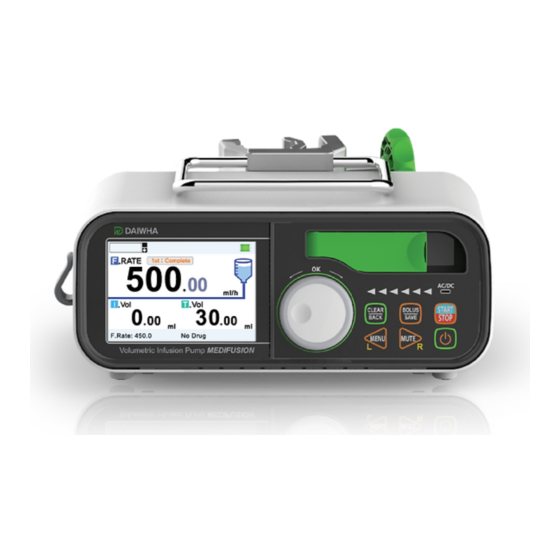
Names and Functions Names and Functions Front panel Name Function Door Clamp Use to open or close the door. It`s blinking from right to left indicates that injection is in progress. Injection display LED (Green) With only right LED turned on, it indicates that injection is stopped in standby mode. -
Page 13: Rear Panel
Names and Functions Rear panel Name Lock Nurse Call Connector Drop Sensor Connector USB port (used for maintenance) DC power port Docking Station Connector (To connect an optional Docking Station) Fuse AC power port Open the Cover of Docking Station Connector when using the DOCKING system. -
Page 14: Names And Functions Of Each Button
Names and Functions Names and functions of each button Name Function Turn the JOG dial to choose a menu item or to adjust its value Press the JOG button for saving the adjusted value of a menu item. JOG only moves the cursor from the left to the right in digits. -
Page 15: Lcd Screen Display Region
Names and Functions LCD screen display region Name Name Indicates that Up (↑) & Down (↓) Occlusion is being made. Alarm Paused Indicates that alarm is paused. Purge Indicates that PURGE infusion is being made. Indicates that KVO infusion is being made. Indicates that BOLUS infusion is being made. -
Page 16: Alarm Icon Display Unit
Names and Functions 15 % ~ 25% Battery Low alarm 7 % ~ 15% Battery Empty alarm Battery Low status (shown in red) ~ 7 % Battery Empty stat Being Charged Charging Complete Connected to DC p ower When the DC power is connected, the product operates without charging. Caution Alarm icon display unit The Alarm Icon Display unit checks each sensor and displays the state of the pump. -
Page 17: Information Display Unit
Names and Functions Name Description IV SET This is displayed in red when an I.V Set is not installed. Information display unit Displays the I.V Set installed in the pump and the set drug. Name Description Displays name of the fluid set (I.V Set). I.V Set R. - Page 18 Names and Functions Name I.V Set Holder Air Sensor Slide Clip home Manual Clamp Down Occlusion Sensor Door Latch Pumping Unit Up Occlusion Sensor...
-
Page 19: Components
Names and Functions Components Name Image Power cable User Manual Drop Sensor (sold separately) -
Page 20: Installation
Installation Installation Mounting the product and connecting the power 1. Connection the I.V Pole stand Turn the pole handle of the pole clamp to fix to the I.V Pole stand. Use the product in a horizontal position. The product can be used in a vertical position in case of emergency or depending on the operating environment. -
Page 21: Connecting The External Power
Installation Connecting the external power 1. Connect the power cord to the AC power jack on the rear of the product. Then the AC/DC LED (orange color) on the Front turns on. 2. Press the POWER button on the front of the product. -
Page 22: Mounting I.v Set
Installation Mounting I.V Set 1. Place the roller clamp of the I.V Set at the lower side of the product and lock it. Insert the guide needle into the I.V bag and fill the chamber of the set with I.V liquid up to 1/3 or 1/2. - Page 23 Installation 9. Open the roller clamp of the I.V Set. 10. Remove air in the tube and check for leakage, and then insert the needle into the patient’s vein. 11. Configure settings for KEYPAD by using JOG dial, and then press the START button.
-
Page 24: Mounting The Drop Sensor (Optional)
Installation Mounting the drop sensor (optional) 1. Connect the drop sensor to the DROP/PCA (drop sensor port) located on the rear of the product. Do not connect the drop sensor to the NURSE Call port. 2. Place the drop sensor between the chamber nozzle of the I.V Set and the fluid surface in the chamber. - Page 25 Installation 4. When handling the drop sensor, always keep the chamber surface of the I.V Set that is located between the drop sensors in a clean condition. Be careful not to get dirt on the chamber. The number of drops may not be counted due to the dirt.
-
Page 26: Injection Modes
Injection Modes Injection Modes Settings for each injection mode Injection Mode & Settings Description Flow rate F.Rate (ml/h) and T.Vol (ml) are set for the infusion. setting Normal Injection Mode Infusion time Infusion time, F.Rate (ml/h), and T.Vol (ml) are set for the infusion. -
Page 27: Normal Infusion
Injection Modes Normal Infusion Use the JOG dial and KEYPAD to change the settings for F.Rate, T.VOL, and R.TIME. 4.2.1 Setting the flow rate and total volume 1. Select F.Rate and press the JOG in standby mode. 2. The flow rate setting appears in red with the cursor. -
Page 28: Setting The Remaining Time
Injection Modes 5. Turn the JOG dial button to set the T.Vol value or use the MENU(left)/MUTE(right) to move the digit, and then press the JOG or SAVE button to set ok. Then the flow rate and total volume are set. ... - Page 29 Injection Modes 3. Turn the JOG dial or use the MENU(left)/ MUTE(right) button to set the time The R.Time setting screen appears in red with the cursor. 4. Press the JOG or SAVE to set ok. 5. Press the START button to start injection.
-
Page 30: Drug Infusion
Injection Modes Drug Infusion Choose the drug in drug library and change the settings for Weight, Dose and T.VOL by using the JOG and the KEYPAD as in injection mode. 1. Press the MENU button in the injection standby screen. ... -
Page 31: Dosage Infusion
Injection Modes 5. Press the START button to start injection. Dosage Infusion Change the settings manually for Concentration and Dose value by using the JOG and the KEYPAD. 1. Press the MENU button in the injection standby screen. Then the MENU screen appears. ... -
Page 32: Secondary Injection Mode
Injection Modes 4. Use the JOG to adjust the value of Concentration, Weight, Dose, and T.Vol and press the JOG to set ok. The setting range of Weight is 0.1-300kg. It is set as 0.1-99.9 kg (step of 0.1 kg), 1-300 kg (step of 1 kg). - Page 33 Injection Modes 2. Press the JOG to move to the sub menu. Use the JOG to select Secondary Mode. 3. At the first stage, Auto Mode can be selected. Pressing Start on screen: After primary injection, it is set to automatically change to the secondary injection mode.
-
Page 34: Infusion Relay Mode
Relay can be set to Auto and Manual. Relay only operates in Docking Station. The company-provided syringe pump (DS-5000) and infusion pump (DI-6000) are compatible and can be used together. Infusion relay is for single use only and the pump does not stay relayed after completion. - Page 35 Injection Modes 2. Select Infusion Relay in the sub menu. First, Master pump (Slot No.1) screen appears. 3. Enter the Slave slot number and press the JOG or SAVE button. 4. Select Slave in the sub menu. Slave pump (Slot No. 2) screen appears. 5.
-
Page 36: Operation
Operation Operation Operate the product in a safe indoor place. Before use, read through the descriptions for each operation status and corresponding cautions. Power on/off 1. Press the POWER button on the front of the product to turn on the power. -
Page 37: Standby Status (Before Operation)
Operation Standby status (before operation) In this status, if you press the START button in standby mode, operation is immediately started. With I.V Set being loaded, the pump can be changed to the standby mode by pressing the POWER button for 3 seconds. -
Page 38: Infusion Start (Operation Started) And Stop
Operation Infusion start (operation started) and stop Press the START button on the front of the product to start operation. Infusion animation operates on the LCD screen, and infusion LED blinks sequentially. When you press the START/STOP button while in normal operation (injecting or BOLUS injection in progress), injection is stopped and the infusion animation and the green LED turns off. -
Page 39: Bolus (Purge) Injection Mode
Operation 5.4.2 Bolus (Purge) Injection Mode Operation Status Description Display Bolus Emergency injection during the infusion Purge Emergency injection during the standby status A preset pop-up window appears Auto Bolus by pressing the BOLUS button. Select Start button to start Bolus Auto Bolus injection or Modify to adjust F.Rate and T.Vol. -
Page 40: Viewing The Infused Volume And Remaining Time
Operation Press the CLEAR button again to restart the infusion. 3. Press the JOG or BOLUS button. Then the changed flow rate is applied and injection is started again. This function changes the flow rate during injection. Set the value with caution. -
Page 41: Standby Time Function
Operation Infused Vol: 0-9999.9 Types of warning alarms The event logs appear on the LCD display. See Service Manual for more details. The alarm log function saves records of alarm set in memory. The alarm events can be written up to 50 records and are saved in the memory other than the History Log memory. - Page 42 Operation The VTBI function can be used after setting in the Infusion Setting menu. See 6.2 Infusion Setting/K.V.O F.Rate...
-
Page 43: Custom Settings
Custom Settings Custom Settings Menu list The Menu consists of Infusion Setting, Dosage Setting, Device Setting and Service Mode. Name Description You can perform functions for I.V Set selection, Bolu Infusion Setting sF.Rate, Bolus Volume, K.V.O F.Rate, Secondary Mode and Infusion Relay. You can set for F.Rate calculation, drug library, and Dosage Setting drug registration. - Page 44 Custom Settings...
-
Page 45: Infusion Setting
Custom Settings Infusion Setting Infusion Setting in the DI-6000 model provides menus such as I.V Set Select, Bolus F.Rate/Volumn, K.V.O F.Rate, Secondary Mode, and Infusion Relay. Description Name Selects the registered I.V Set I.V Set Select Changes the manufacturer for the mounted I.V Set if needed. -
Page 46: Dosage Setting
Custom Settings Description Name function. Its setting is for single use only. So it must be set for each use. ▪ See 4.6 Infusion Relay Mode Make sure that the I.V set is available. If inappropriate I.V set is used, an ... -
Page 47: Device Setting
Custom Settings Device Setting The Device Setting includes the menus for Alarm & Volume, Sensor, History and Etc. Name Description Sets the function for Standby Alarm, Near Complete Alarm, Alarm & Volume AC/DC Remove Alarm, and Key Volume. Sets the function for Up Occlusion level, Down Occlusion level, Sensor Air Size, and Drop Sensitivity. -
Page 48: Sensor
Custom Settings AC/DC Remove Used to set the alarm to On or Off when the AC/DC po wer cable is connected or disconnected. Alarm Used to set the alarm and sound volume. Alarm Volume Setting range is 1 ~ 10 steps. (50dB ~ 67dB) Key Volume Used to set the button sound volume. - Page 49 Custom Settings Save ON: The volume to be injected and the flow rate are saved. When the power is turned off and on, that appears. Save OFF: The volume to be injected and the flow rate are lost, when the power is turned off and on, the data appears with 0.
-
Page 50: Default Value
Custom Settings Default value The default value of the menu is as following. Menu Default values Bolus F.Rate 700 ml/h Infusion Setting Bolus Volume 5 ml K.V.O F.Rate 0.1 ml/h Standby Alarm Near Complete Alarm AC/DC Remove Alarm Alarm Volume Key Volume UP Occlusion Level Down Occlusion Level... -
Page 51: Service Mode
Custom Settings Service Mode Biomedical engineers and service technicians can use Service Mode to perform various inspections of the device. Name Description Power Check the SMPS and Battery status. Motor Advance or retract motors to check the checkers. Set the default value for device occlusion level. Check occlus Occlusion ion level changes. -
Page 52: Access Service Mode
Custom Settings 6.6.1 Access Service Mode Hold the JOG pressing and press the POWER button at the same time to access Service Mode from the main menu screen. Access to the sub-menus under Service Mode requires a password. Enter the password as follows. 1 Enter the password (1711). -
Page 53: Alarms And Actions
Alarms and Actions Alarms and Actions Alarms are triggered when the product is not functioning as intended. The following describes required actions for each alarm. The system automatically stops injection when an alarm occurs (according to the priority). Be sure to check alarm messages, indication lamps, and alarm sounds to determine required actions. -
Page 54: Alarm Priorities
Alarms and Actions Alarm priorities The Table below describes the priorities for main alarms. There are 3 levels of severity to indicate their urgency. Severity Alarm Color of LCD Down Occlusion Alarm Up Occlusion Alarm Air Alarm HIGH Door (Open) Alarm (Flickering frequency - 2Hz) Drop (Sensor) Alarm Battery Overheating Alarm... -
Page 55: Up Occlusion Alarm
Alarms and Actions Up occlusion alarm Description Item When the clamp on the upper part of the pump is closed, this alarm occurs due to the pressure below the negative set pressure. Cause When the line of the I.V Set is twisted, the set is mounted incorrectly, or the needle blockage occurs, injection stops and the UP occlusion alarm occurs. -
Page 56: Door Open Alarm
Alarms and Actions Description Item Alarm clearing Press any buttons to clear the air bubble alarm. method Make sure that the I.V Set is free of air when an air bubble alarm occurs Action before use. Door open alarm Description Item ... -
Page 57: Battery Overheating Alarm
Alarms and Actions When the drop sensor is connected or disconnected during injection, an alarm sounds and the message, “Drop,” is displayed and disappears on the LCD display. Battery Overheating Alarm Description Item When the temperature of the battery is over 45 degrees or above, battery Cause overheating alarm occurs. -
Page 58: Low Battery Alarm
Alarms and Actions 7.10 Low battery alarm Description Item When the product is run on battery and the remaining operation time is 30 Cause minutes before stop, a low battery alarm occurs. Alarm sounds Alarm screen appears in yellow on the Indicators LCD display. -
Page 59: Complete Alarm
Alarms and Actions Description Item Alarm sounds Alarm screen appears in yellow on the Indicators LCD display. LCD state display: “K.V.O” Press any buttons to clear the K.V.O alarm Alarm clearing method If not cleared, the alarm sound will be heard every 15 seconds. 7.13 Complete Alarm 구분... -
Page 60: Standby Alarm
Alarms and Actions Description Item Alarm sounds Alarm screen appears in yellow on Indicators the LCD display. LCD state display: “Near Complete” Alarm clearing Press any buttons to clear the near complete alarm. method When injection is ended up to the volume to be infused the alarm is ... -
Page 61: Error Codes
Alarms and Actions Description Item Alarm sounds Alarm screen appears in yellow on the Indicators LCD display. LCD state display: “Time Out” Alarm clearing If any button is pressed, the time out alarm is cleared and the injection method standby screen appears. - Page 62 Alarms and Actions Err Code Display Cause Screen E004 Battery Error Note Make sure the I.V Set is properly installed. Contact your dealer regarding any malfunction or error. Caution...
-
Page 63: Maintenance And Storage
Maintenance and Storage Maintenance and Storage Regular inspection and maintenance of the pump is crucial for prolonged safe use. If any failure is found during inspection or maintenance, stop using the pump and contact your dealer. If the product is hit or dropped, stop using it and contact your dealer. This may ... -
Page 64: Storage
Maintenance and Storage Remove the power cable from the product for cleaning. Do not use an autoclave or E.O gas for disinfection. Do not use thinner, solvent, benzene, ammonia, or acetone for cleaning. Use a Caution damp cloth. ... -
Page 65: Technical Specification
Technical Specification Technical Specification Specifications Product name Electrically-powered infusion pump Model name MEDIFUSION DI-6000 Principle of injection Peristaltic transit finger Flow rate 0.01 ~ 1500 ml/h ▪ ±5 % (BD I.V Set, AN122) ▪ It is measured every hour after operation with water or saline water Accuracy (flow rate of 1.0 ml/h or higher) at room temperature (25 ºC). - Page 66 Technical Specification Product name Electrically-powered infusion pump –2600 mA/h, 3.7V*3EA –Use time: Approx. 10 hours (at flow rate of 25 ml/h) –Charge time: Approx. 6 hours Power consumption 34 VA ▪ Electrical shock protection type: Class I Protection type ▪ Electrical shock protection level: TYPE CF ▪...
-
Page 67: Functional Specifications
Technical Specification Functional specifications Description Function Air bubble alarm Down-Steam Occlusion alarm Up-Stream occlusion alarm Door Open Alarm Low battery alarm, empty battery alarm AC/DC removal power alarm Alarm Standby alarm (interval of 2 minutes, with no injection in progress) ... -
Page 68: Occlusion Detection Properties
Technical Specification Occlusion detection properties The company measured the occlusion pressure, alarm time, and Bolus volume at a flow rate of 25 ml/h. I.V Set used: BD AN122 (ambient temperature: 25 ºC) Measurement position: The closed clamp was located 1 meter below the pump ... -
Page 69: Memory Function
Technical Specification Manufacturer I.V Set Model Code Name SEWWOON MEDICAL 4934-001 SEW-4934-001 SINCHANG MEDICAL A1106 SC-A1106 HYUPSUNG MEDICAL HS-IV-104T HS-IV-104T Various I.V Sets are supported through continuous update. Actual infusion volumes may vary depending on the type of I.V Set. Caution Memory Function ... -
Page 70: Drop Sensor Functions
Technical Specification Connect the equipment into an outlet on a circuit different from that to which the other device(s) are connected. Consult the manufacturer or field service technician for help. Drop sensor functions Detects free flow caused by malfunctioning. Detects no drop caused by container depletion or tube occlusion. - Page 71 Technical Specification...
-
Page 72: Appendix
10.1 EMC declaration Guidance and Manufacturer's Declaration - electromagnetic emissions Infusion Pump DI-6000 is intended for use in the electromagnetic environment specified below. The customer or user of the pump should assure that it is used in such an environment. - Page 73 Appendix Guidance and Manufacturer's Declaration - electromagnetic immunity Infusion Pump DI-6000 is intended for use in the electromagnetic environment specified below. The customer or user of the pump should assure that it is used in such an environment. IEC 60601-1-2...
- Page 74 Appendix IEC 60601-1-2 Compliance Electromagnetic Immunity Test environment - guidance Test Level Level Conducted RF 3 Vrms = 3 Vrms IEC 61000-4-6 Outside the ISM bands, 150 kHz to 80 MHz a) 10 Vrms Within the ISM bands, 150 kHz to 80 MHz a) Radiated RF 3 Vrms = 3V/m...
- Page 75 RF transmitters, an electromagnetic site survey should be considered. If the measured field strength in the location in which Infusion Pump DI-6000 is used exceeds the applicable RF compliance level above, the device should be observed to verify normal operation.
-
Page 76: Document History
Appendix communications equipment could cause interference if it is inadvertently brought into patient areas. Note 4 - These guidelines may not apply in all situations. Electromagnetic propagation is affected by absorption and reflection from structures, objects and people. 10.2 Document History Changes Date Revision...
Need help?
Do you have a question about the DI-6000 and is the answer not in the manual?
Questions and answers