Table of Contents
Advertisement
Quick Links
Advertisement
Table of Contents

Summary of Contents for IPP Pump Products iLobe Series
- Page 1 Operating Instructions iLobe Rotary lobe pump Doc. No. 0179 – status 03/2017...
-
Page 2: Table Of Contents
Operating instructions Date: 15.03.2017 Page 2 of 63 iLobe Doc. No. 0179 Rotary Lobe Pump Est: D. Lünnemann / W. Stein Content How to consult and keep this documentation ................5 Used symbols..........................6 Used tags ............................6 Terms and definitions ......................... 7 Intended use .......................... - Page 3 Operating instructions Date: 15.03.2017 Page 3 of 63 iLobe Doc. No. 0179 Rotary Lobe Pump Est: D. Lünnemann / W. Stein 10.13.1 Overview barrier pressure tank ....................22 10.13.2 Assembly and connection of the tank ..................23 10.13.3 Selection of barrier fluid ......................24 10.13.4 Filling and emptying the tank .....................
- Page 4 Operating instructions Date: 15.03.2017 Page 4 of 63 iLobe Doc. No. 0179 Rotary Lobe Pump Est: D. Lünnemann / W. Stein Cross-sectional drawing ......................48 Parts list ............................48 Dimensions ..........................49 18.1 Horizontal execution ....................... 49 18.2 Vertical execution ........................50 18.3 Material specifications ......................
-
Page 5: How To Consult And Keep This Documentation
GmbH reserves all rights related to this use and maintenance manual and with the object presented therein. The receiving party recognises these rights to IPP Pump Products GmbH in the person of its legal representative, Mr. Thomas Moldenhauer, and undertakes, in the absence of an explicit written consent, no to make it accessible to others, either in whole or in part and, not to use it outside the purpose for which it was created. -
Page 6: Used Symbols
Operating instructions Date: 15.03.2017 Page 6 of 63 iLobe Doc. No. 0179 Rotary Lobe Pump Est: D. Lünnemann / W. Stein DANGER All technical documentations regarding the iLobe rotary lobe pump have to be kept at an easily accessible place so that they can be consulted quickly. Furthermore the personnel responsible for the operation and maintenance have to be informed about the place where the documentation is kept. -
Page 7: Terms And Definitions
Please note that the markings / tags at the iLobe rotary pump may not be changed or removed. WARNING It is not allowed to use any IPP Pump Products GmbH item without its identification plate. Should an item be without its identification plate the customer has to contact IPP Pump Products GmbH technical office so that the item can be identified and a new identification plate can be issued. - Page 8 Operating instructions Date: 15.03.2017 Page 8 of 63 iLobe Doc. No. 0179 Rotary Lobe Pump Est: D. Lünnemann / W. Stein WARNING! All work on and with the pump must always be in accordance with all the prevailing standards regarding occupational health and safety as well as machine safety.
-
Page 9: Intended Use
Any damages resulting from this will void responsibility of the manufacturer and the user bears the full risk. Please contact IPP Pump Products GmbH if the pump shall be used for any other application or at any other conditions than those which are part of the agreed specifications according to which the pump had been selected. -
Page 10: Introduction
This manual represents the most recent information regarding the pump types mentioned in this manual at the time printing. IPP Pump Products GmbH reserves the right to modify the construction of the mentioned pump types as well as the contents of this manual without prior or afterward notification. -
Page 11: How To Identify The Pump
Manufacturer Die iLobe – Rotary lobe pumps are manufactured by IPP Pump Products GmbH Feldmühlenweg 6 - 10 D- 49593 Bersenbrück Phone +49 (0) 5439-80921-0 Fax. -
Page 12: Precautions
Operating instructions Date: 15.03.2017 Page 12 of 63 iLobe Doc. No. 0179 Rotary Lobe Pump Est: D. Lünnemann / W. Stein 7.3 Precautions When performing maintenance work to the pump ensure that the drive motor is shut down and cannot be switched on unintentionally! ... -
Page 13: Shaft Seals
Operating instructions Date: 15.03.2017 Page 13 of 63 iLobe Doc. No. 0179 Rotary Lobe Pump Est: D. Lünnemann / W. Stein 8.2.2 Shaft seals The following shaft seals are available: Single mechanical seal Double mechanical seal with flushing or quench (with or without pressure) ... -
Page 14: Main Components
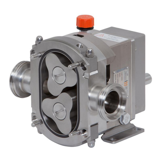
Operating instructions Date: 15.03.2017 Page 14 of 63 iLobe Doc. No. 0179 Rotary Lobe Pump Est: D. Lünnemann / W. Stein 9 Main components The pump with its main components: Pump case Bearing case Frontal tapered roller bearing Rear tapered roller bearing Mechanical seal Driving shaft... -
Page 15: Installation
Operating instructions Date: 15.03.2017 Page 15 of 63 iLobe Doc. No. 0179 Rotary Lobe Pump Est: D. Lünnemann / W. Stein 10 Installation 10.1 General information The foundation must be solid, flat and even. The area in with the pump unit is placed, must be well vented. Too high temperature, air humidity or a dusty atmosphere may have negative effects to the performance of an electric motor. -
Page 16: Lifting
Operating instructions Date: 15.03.2017 Page 16 of 63 iLobe Doc. No. 0179 Rotary Lobe Pump Est: D. Lünnemann / W. Stein 10.4 Lifting If an appropriate lifting device is available, this shall be used for lifting the pump / pump unit. DANGER It is not allowed to stand under suspended loads! If the pump is assembled with a motor on a base plate the hoisting slings for lifting the pump unit are... -
Page 17: Installation Dimensions
The correct installation dimensions of the pump unit are part of the unit drawing which has been supplied with the pump or which can be obtained at IPP Pump Products GmbH. For details regarding the most important dimensions of the bare shaft pump, please refer to chapter 18 of this manual. -
Page 18: General
Operating instructions Date: 15.03.2017 Page 18 of 63 iLobe Doc. No. 0179 Rotary Lobe Pump Est: D. Lünnemann / W. Stein 10.7.1 General Ensure that the piping system is sufficiently supported, especially at the inlet and outlet ports. The piping must not weigh on the pump. -
Page 19: Pump With Pressure Relief Valve
Operating instructions Date: 15.03.2017 Page 19 of 63 iLobe Doc. No. 0179 Rotary Lobe Pump Est: D. Lünnemann / W. Stein 10.9 Pump with pressure relief valve If the pump is fitted with a pressure relief valve at the pump cover it is compulsory to install a pressure gauge at the pressure side and a shut-off valve directly after the pressure gauge. -
Page 20: Alignment Tolerances
Operating instructions Date: 15.03.2017 Page 20 of 63 iLobe Doc. No. 0179 Rotary Lobe Pump Est: D. Lünnemann / W. Stein 10.10.2 Alignment tolerances The following table with its corresponding figure shows the tolerance limits for aligning the coupling: Outside diameter A must be Max. -
Page 21: Connection Of The Pipes
Operating instructions Date: 15.03.2017 Page 21 of 63 iLobe Doc. No. 0179 Rotary Lobe Pump Est: D. Lünnemann / W. Stein 10.11 Connection of the pipes DANGER Ensure that the motor CANNOT be started during any works carried out at the pump unit and with the rotating parts not completely covered! ATTENTION The pipe system must ALWAYS be CLEANED respectively free of solid matters! After the new... -
Page 22: Barrier Pressure Tank / Barrier Fluid Tank
Operating instructions Date: 15.03.2017 Page 22 of 63 iLobe Doc. No. 0179 Rotary Lobe Pump Est: D. Lünnemann / W. Stein 10.13 Barrier pressure tank / Barrier fluid tank The barrier pressure tank is delivered from the factory without barrier fluid. To avoid damages to the mechanical seals the barrier pressure tank must be filled with a suitable liquid before start-up of the pump. -
Page 23: Assembly And Connection Of The Tank
Operating instructions Date: 15.03.2017 Page 23 of 63 iLobe Doc. No. 0179 Rotary Lobe Pump Est: D. Lünnemann / W. Stein 10.13.2 Assembly and connection of the tank In general the barrier pressure tank is delivered connected to the pump with hoses and fixed onto the base plate. -
Page 24: Selection Of Barrier Fluid
Operating instructions Date: 15.03.2017 Page 24 of 63 iLobe Doc. No. 0179 Rotary Lobe Pump Est: D. Lünnemann / W. Stein If the pump position is vertical the flush pipes can only be connected in parallel. The feed must be at the bottom part and the return at the top part of the pump. -
Page 25: Filling And Emptying The Tank
Operating instructions Date: 15.03.2017 Page 25 of 63 iLobe Doc. No. 0179 Rotary Lobe Pump Est: D. Lünnemann / W. Stein 10.13.4 Filling and emptying the tank DANGER Never open a barrier pressure tank under pressure. Before opening the barrier pressure system must always be completely depressurized. -
Page 26: Direction Of Rotation
Operating instructions Date: 15.03.2017 Page 26 of 63 iLobe Doc. No. 0179 Rotary Lobe Pump Est: D. Lünnemann / W. Stein 10.14 Direction of rotation ATTENTION Never operate the pump without pump cover or without being connected to the pipes! Before connecting the drive to the power supply, the correct direction of rotation of the drive shaft must be established. -
Page 27: Filling With Oil
Operating instructions Date: 15.03.2017 Page 27 of 63 iLobe Doc. No. 0179 Rotary Lobe Pump Est: D. Lünnemann / W. Stein 10.16 Filling with oil The gearbox of a new pump has been filled with oil by the manufacturer! Unscrew the venting plug together with the oil dipstick. Fill the oil through the filling opening into the gearbox. -
Page 28: Commissioning
For a correct fitting and disassembly of the rotors, please refer to the instructions in chapter 13.6 and 13.7. Rotor dummies are available at IPP Pump Products GmbH. 11.2 Control Please check if there’s enough oil in the gearbox. The oil level must be between the top and bottom limit marked at the oil dipstick. -
Page 29: Start-Up
Operating instructions Date: 15.03.2017 Page 29 of 63 iLobe Doc. No. 0179 Rotary Lobe Pump Est: D. Lünnemann / W. Stein 11.3 Start-up Open – if existing – the non-return valves of the flushing pipes. Open – if existing – the non-return valve at the outlet. ... -
Page 30: Maintenance
Operating instructions Date: 15.03.2017 Page 30 of 63 iLobe Doc. No. 0179 Rotary Lobe Pump Est: D. Lünnemann / W. Stein 12 Maintenance 12.1 General The following points have to be checked regularly: Perfect functioning of the pump. Excessive noise can be caused by worn bearings, problems at the gear wheels, galling rotors or cavitations. -
Page 31: Precautions
Operating instructions Date: 15.03.2017 Page 31 of 63 iLobe Doc. No. 0179 Rotary Lobe Pump Est: D. Lünnemann / W. Stein 13.2 Precautions DANGER Never let the pump run without pump cover or without having the pipes connected appropriately! DANGER It must be ensured that the drive of the pump is switched off during maintenance works and cannot be re-started unintentionally! DANGER... -
Page 32: Oil Drainage
Operating instructions Date: 15.03.2017 Page 32 of 63 iLobe Doc. No. 0179 Rotary Lobe Pump Est: D. Lünnemann / W. Stein If there is no more liquid leaking re-tighten the cap nuts by hand. 13.5 Oil drainage Place a collection tank under the drainage opening of the gearbox cover. ... -
Page 33: Disassembly Of The Rotors
Operating instructions Date: 15.03.2017 Page 33 of 63 iLobe Doc. No. 0179 Rotary Lobe Pump Est: D. Lünnemann / W. Stein 13.7.1 Disassembly of the rotors Remove the cap nuts and pull off the pump case cover and the o-ring respectively profile shape gasket. - Page 34 Operating instructions Date: 15.03.2017 Page 34 of 63 iLobe Doc. No. 0179 Rotary Lobe Pump Est: D. Lünnemann / W. Stein The other parts of the shaft seals are disassembled as follows: Insert a screw driver on both sides of the shaft into the assembling openings on both sides of the pump case.
-
Page 35: Disassembly Of The Gearbox
Operating instructions Date: 15.03.2017 Page 35 of 63 iLobe Doc. No. 0179 Rotary Lobe Pump Est: D. Lünnemann / W. Stein 13.7.3 Disassembly of the gearbox Continue the disassembly as follows: Ensure that there is no more oil left in the gearbox! Remove the feather key out of the driving shaft. - Page 36 Operating instructions Date: 15.03.2017 Page 36 of 63 iLobe Doc. No. 0179 Rotary Lobe Pump Est: D. Lünnemann / W. Stein Unlock the groove nuts of the gear wheels and loosen the groove nuts. Pull of the gear wheels from the shafts. A puller or a lever may be a helpful tool. Remove the feather keys.
-
Page 37: Control Of The Parts
13.7.4 Control of the parts Only use original - IPP Pump Products GmbH –parts for replacement of defective parts. Check all radial shaft seals for leakages and damages. Check all non-defective for scratches, burrs, debris or excessive wear. -
Page 38: Assembly Of The Pump
Pretension the bearing by mounting the lock washer and tighten the shaft nut. The pretension must be adjusted to the following friction torques of the bearing: We recommend using a torque gauge. If required, please contact IPP Pump Products GmbH. Please adjust the following friction torques:... - Page 39 Operating instructions Date: 15.03.2017 Page 39 of 63 iLobe Doc. No. 0179 Rotary Lobe Pump Est: D. Lünnemann / W. Stein Insert the feather keys and press the shafts into the bearing case (use a press). Now place the bearing covers onto the shaft ends. Don’t tighten the bearing covers yet. Now install the gear wheels and tighten them and lock the screwing.
-
Page 40: Mechanical Seals
Operating instructions Date: 15.03.2017 Page 40 of 63 iLobe Doc. No. 0179 Rotary Lobe Pump Est: D. Lünnemann / W. Stein Place the bearing case with the shafts onto the pump case. Pay attention when passing the shafts: the radial shaft seals can easily be damaged. Place the pump onto the pump feet and tighten the bearing case. - Page 41 Operating instructions Date: 15.03.2017 Page 41 of 63 iLobe Doc. No. 0179 Rotary Lobe Pump Est: D. Lünnemann / W. Stein Push the seal housing into the pump case so that the pins fit into the slots provided for these. The slots are in one line with the leakage holes.
-
Page 42: Lip Seals
Operating instructions Date: 15.03.2017 Page 42 of 63 iLobe Doc. No. 0179 Rotary Lobe Pump Est: D. Lünnemann / W. Stein ATTENTION No excessive force is needed to install the mechanical seal provided that all parts are engaged to each other appropriately. Check the spring functioning before installing the rotors. 13.8.1.2 Lip seals Insert the insection sleeve and the lip seal one after another onto the shaft. - Page 43 Operating instructions Date: 15.03.2017 Page 43 of 63 iLobe Doc. No. 0179 Rotary Lobe Pump Est: D. Lünnemann / W. Stein Now install the mechanical seal housing. Insert the wave spring as well as the o-ring for the fixed sliding ring of the atmosphere side. Ensure that the wave spring lies between the two rows of cylindrical pins for the rotating locking.
- Page 44 Operating instructions Date: 15.03.2017 Page 44 of 63 iLobe Doc. No. 0179 Rotary Lobe Pump Est: D. Lünnemann / W. Stein Insert the mechanical seal housing into the pump case. NOTE First the sliding surfaces of both atmosphere side sliding rings must be cleaned and free of grease. The pins of the rotating locking must fit into the grooves provided for that.
-
Page 45: Tightening Torques
Operating instructions Date: 15.03.2017 Page 45 of 63 iLobe Doc. No. 0179 Rotary Lobe Pump Est: D. Lünnemann / W. Stein ATTENTION No excessive force is needed to install the mechanical seal provided that all parts are engaged to each other appropriately. Check the spring functioning before installing the rotors. Now install the rotors. -
Page 46: Decommissioning
Operating instructions Date: 15.03.2017 Page 46 of 63 iLobe Doc. No. 0179 Rotary Lobe Pump Est: D. Lünnemann / W. Stein Insert the flat gasket and ensure clean and even surfaces without residues. Install the gear box cover on the bearing housing. Be careful when passing through the shaft in order not to damage the radial shaft seals. -
Page 47: Disposal
Operating instructions Date: 15.03.2017 Page 47 of 63 iLobe Doc. No. 0179 Rotary Lobe Pump Est: D. Lünnemann / W. Stein 14.3 Disposal If the pump should be scrapped the following points must be observed: Clean the pump case inside if there could be residues of the pumped liquid. Drain the oil completely of the gear box. -
Page 48: Cross-Sectional Drawing
Operating instructions Date: 15.03.2017 Page 48 of 63 iLobe Doc. No. 0179 Rotary Lobe Pump Est: D. Lünnemann / W. Stein 16 Cross-sectional drawing 17 Parts list Pos. Description Quantity Pos. Description Quantity Mechanical seal housing Shaft nut 1.10 Spacer bushing I Tab washer 1.10.1 Driving pins spacer bushing... -
Page 49: Dimensions
Operating instructions Date: 15.03.2017 Page 49 of 63 iLobe Doc. No. 0179 Rotary Lobe Pump Est: D. Lünnemann / W. Stein 18 Dimensions 18.1 Horizontal execution iL55 iL63 iL85 iL115 iL42 sx/sxx DN 25 DN 15 DN20 DN25 DN 32 DN 40 DN 40 DN 40 DN 40 DN 40 DN 50 DN 65 DN 50 DN 65 DN 80 DN 100 49,5 34,5 38,5... -
Page 50: Vertical Execution
Operating instructions Date: 15.03.2017 Page 50 of 63 iLobe Doc. No. 0179 Rotary Lobe Pump Est: D. Lünnemann / W. Stein 18.2 Vertical execution iL55 iL63 iL85 iL115 sx/sxx DN 15 DN 20 DN 25 DN 32 DN 40 DN 40 DN 40 DN 40 DN 40 DN 50 DN 65 DN 50 DN 65 DN 80 DN 100 165,5 165,5 165,5... -
Page 51: Material Specifications
Operating instructions Date: 15.03.2017 Page 51 of 63 iLobe Doc. No. 0179 Rotary Lobe Pump Est: D. Lünnemann / W. Stein 18.3 Material specifications Pos. No. Description Materials: Material no. Pump case cover Stainless steel 1.4404 Rotor screw Stainless steel 1.4404 Bearing housing ST52... -
Page 52: Double Mechanical Seal
Operating instructions Date: 15.03.2017 Page 52 of 63 iLobe Doc. No. 0179 Rotary Lobe Pump Est: D. Lünnemann / W. Stein 18.3.1.2 Double mechanical seal Pos. Description Quantity Rotary Seal Face, Product Seal Stationary Seal Face, Product Seal Wave Spring Seal Housing Double Mecanical Seal Anti-Rotation Pins, Seal Housing, Double Mech. -
Page 53: Lip Seal
Operating instructions Date: 15.03.2017 Page 53 of 63 iLobe Doc. No. 0179 Rotary Lobe Pump Est: D. Lünnemann / W. Stein 18.3.1.3 Lip seal Pos. Description Quantity 1.21 Radial shaft seal 1.22 Shaft protection bush 1.23 O-ring 1.24 Ejection bush 19 Pressure relief valves 19.1 Effect, purpose and hygienic suitability In order to protect the pump and the factory there are pressure relief valves available for the integration into... -
Page 54: Pressure Relief Valve Integrated Into The Pump Cover, Spring Loaded
Operating instructions Date: 15.03.2017 Page 54 of 63 iLobe Doc. No. 0179 Rotary Lobe Pump Est: D. Lünnemann / W. Stein 19.1.1 Pressure relief valve integrated into the pump cover, spring loaded closed opened closed 19.1.2 Pressure relief valve integrated into the pump cover, pressure loaded and controlled by compressed air closed opened... -
Page 55: Adjustment
Operating instructions Date: 15.03.2017 Page 55 of 63 iLobe Doc. No. 0179 Rotary Lobe Pump Est: D. Lünnemann / W. Stein 19.2 Adjustment The hydraulically loaded surface of the pressure relief valve corresponds to app. ½ of the valve piston surface when the pump is running. -
Page 56: Pressure Relief Valve With Built-In Temperature Sensor
Operating instructions Date: 15.03.2017 Page 56 of 63 iLobe Doc. No. 0179 Rotary Lobe Pump Est: D. Lünnemann / W. Stein 19.4 Pressure relief valve with built-in temperature sensor Generally, positive displacement pumps must be protected against excessive overpressure. Excessively high overpressure might be caused by an obstruction in the discharge line, by solidifying or cooling of the pumped fluid, by modification of the pumped fluid or by wrong pre-setting of the speed. - Page 57 Operating instructions Date: 15.03.2017 Page 57 of 63 iLobe Doc. No. 0179 Rotary Lobe Pump Est: D. Lünnemann / W. Stein The recognition of changes of sensor measured values caused by an error is of particular importance for a later SIL consideration. The corresponding performance level respectively SIL results from the risk analysis (risk graph), which must be issued respectively stipulated by the user of the pump.
-
Page 58: Parts List
Operating instructions Date: 15.03.2017 Page 58 of 63 iLobe Doc. No. 0179 Rotary Lobe Pump Est: D. Lünnemann / W. Stein 19.5 Parts list 19.5.1 Spring loaded pressure relief valves Pos. Description Quantity O-Ring pump case cover 9.10.1 Valve housing 9.10.2 Pump cover for pressure relief valve... -
Page 59: 2-Way Pressure Relief Valve Pressure Loaded And Controlled By Compressed Air
Operating instructions Date: 15.03.2017 Page 59 of 63 iLobe Doc. No. 0179 Rotary Lobe Pump Est: D. Lünnemann / W. Stein 19.5.3 2-Way Pressure relief valve pressure loaded and controlled by compressed air Pos. Description Quantity O-Ring seal for pump case cover 9.11.1 Valve cover... -
Page 60: Heatable Pump Case With Integrated Heat Channels Ihch Rc
Operating instructions Date: 15.03.2017 Page 60 of 63 iLobe Doc. No. 0179 Rotary Lobe Pump Est: D. Lünnemann / W. Stein 20.2 Heatable pump case with integrated heat channels IHCh RC In order to improve the heat exchange any iLobe rotary lobe pump can be fitted optionally with integrated heat channels in the pump case. -
Page 61: Trouble Shooting
Operating instructions Date: 15.03.2017 Page 61 of 63 iLobe Doc. No. 0179 Rotary Lobe Pump Est: D. Lünnemann / W. Stein 21 Trouble shooting A malfunction in a pump system may have various causes. The malfunction is not always necessarily in the pump itself, but an also be caused by a malfunction in the piping system or in another fitting in the system. - Page 62 Operating instructions Date: 15.03.2017 Page 62 of 63 iLobe Doc. No. 0179 Rotary Lobe Pump Est: D. Lünnemann / W. Stein Fault Cause Action Wrong direction of Change direction of rotation of rotation motor Pump is not filled with Vent suction line and rotor case and liquid prime rotor case with liquid Insufficient NPSHA...
-
Page 63: Index
Operating instructions Date: 15.03.2017 Page 63 of 63 iLobe Doc. No. 0179 Rotary Lobe Pump Est: D. Lünnemann / W. Stein 22 Index Assembly of the pump unit ..........................19 Connection of the pipes ........................... 21 Coupling ................................19 Decommissioning ............................46 Dimensions Horizontal Port Position..........................
Need help?
Do you have a question about the iLobe Series and is the answer not in the manual?
Questions and answers