Table of Contents
Advertisement
Quick Links
Advertisement
Chapters
Table of Contents

Subscribe to Our Youtube Channel
Related Manuals for HygroMatik FlexLine Spa

Summary of Contents for HygroMatik FlexLine Spa
- Page 1 FlexLine Spa Control Manual ÁFL-TSPA.ENäÈ FL-TSPA.EN E-8881168...
- Page 2 Current version of this manual can be found at: www.hygromatik.co.uk HygroMatik GmbH grants the legal user of this product [or device] the right to use the Work(s) solely within the scope of the legitimate operation of the product [or device]. No other right is granted under this licence.
-
Page 3: Table Of Contents
1. Introduction ........................5 1.1 Typographic Distinctions ....................5 1.2 Documentation ........................5 1.3 Symbols in Use ......................... 5 1.3.1 Specific Symbols related to Safety Instructions ............. 5 1.3.2 General Symbols ......................5 2. Safety Instructions ......................7 2.1 Guidelines for Safe Operation ................... 7 2.1.1 Scope .......................... - Page 4 6.2.1 Setting the language ...................... 25 6.2.2 Input of date and time of day ..................25 6.2.3 Control settings ......................26 6.3 Screen 2 - Main screen ..................... 28 6.3.1 Changing the set point temperature ................28 6.4 Password entry ........................30 6.5 Screen 3 - Main menu (user level) ..................
-
Page 5: Introduction
Retention Please retain these operating instructions in Dear Customer, a secure, always accessible location. If the Thank you for choosing a HygroMatik steam product is resold, turn the documentation generator. over to the new operator. If the documenta- tion is lost, please contact HygroMatik. - Page 6 HygroMatik steam generator. Use for other applications is not permitted. All instructions on intended use, which are given in connec- tion with the basic device, apply. Proper usage also comprises the adherence to the conditions specified by HygroMatik for: • installation • dismantling •...
-
Page 7: Safety Instructions
2. Safety Instructions These safety instructions are required by law. They promote workplace safety and accident Risk of material damage! prevention. The unit may be damaged if switched on repeatedly following a malfunction without 2.1 Guidelines for Safe Opera- prior repair. tion Rectify defects immediately! 2.1.1 Scope... -
Page 8: Mounting, Dismantling, Maintenance And Repair Of The Unit
Use only original fuses with the appropriate amperage rating. The HygroMatik steam humidifier is IP20 pro- Regularly check the unit‘s electrical equip- tected. Make sure that the unit is not object to ment. Promptly repair any damage such as dripping water in the mounting location. -
Page 9: Overview Of The Operation And Layout Of A Steam Bath
3. Overview of the operation and layout of a steam bath There is a danger of electric shock due in The HygroMatik steam generator provides case of non-observance! the steam bath with the steam required for Only safety extra-low voltage (24 V) may be operation. -
Page 10: Layout Of Steam Bath (Schematic Diagram)
3.1 Layout of steam bath (schematic diagram) Position Designation Steam generator Essence peristaltic pump Essence container Essence line to steam hose T-piece for essence injection into steam hose Steam hose Steam manifold in steam bath Supply fan Temperature sensor Exhaust fan Cabin light The following figure shows a simplified diagram of a steam bath - it is not an installation instruction! -
Page 11: Temperature Sensor Usage
Installation under The steam output of the HygroMatik steam a panelling would falsify the measurement generator is controlled by the FlexLine SPA result. control according to the measured tempera- ture. The relative humidity is not measured because it is always 100% after the heating- up phase. -
Page 12: Fan Control
3.4 Fan control 3.4.2 Exhaust fan The influences of the fan control of the supply The exhaust fan is switched on if the temper- and exhaust fans (both in automatic mode) ature set value is exceeded. The exhaust fan are also illustrated in the sample diagram. switches off when the temperature falls below (Temp._set value - exhaust fan 1_∆Temp.). -
Page 13: Sample Diagram For Temperature Profile In Steam Bath
3.5 Sample diagram for tempera- ture profile in steam bath Temperature profile in steam bath Temperature 46.0 °C 45.0 °C 44.0 °C Time Steam production Exhaust fan Supply fan Essence A = essence injection time B = essence pause time Page 13... -
Page 14: Description Of Control
4. Description of control The relay boards are connected to the main- board via a plug system. 4.1 General description The DIN rail relays are connected via cables The control is integrated into the steam with plug. 2 additional relay modules can be humidifier and is operated via a 3.5"... -
Page 15: Mainboard
4.3 Mainboard The mainboard is "the heart" of the control. All logic functions and control operations for the steam humidifier take place here. The relays for the control of the main contac- tor, inlet solenoid valve and blow-down pump are arranged directly on the mainboard. Plugs for relay 1-4 connection... -
Page 16: Connections On The Mainboard
4.3.1 Connections on the mainboard 4.3.1.2 System-side interfaces The use of the connections is illustrated by ST1: the wiring diagrams (see Chapter 8) • 4-pin screw / plug connection for the 4.3.1.1 Customer-side computer connection of L1 and N and the inter- interfaces lock (safety) system Inputs... -
Page 17: Extension Board (Only For Double Cylinder Units)
4.4 Extension board (only for double cylinder units) DIP switches The DIP switches are for CAN-Bus address setting. They are factory preset according to the unit configuration. 4.4.1 Connections on the extension ST08: board Loop-through of ST07 4.4.1.1 Customer-side computer Inputs interfaces ST06:... -
Page 18: Relay Board (Optional)
4.5 Relay board (optional) controlling of additional functional units or options. A maximum of 2 relay boards can be The relay board has three additional relays installed. with potential free break/make contacts (contact load 250 VAC/8 A) for switching or DIP switches The DIP switches are for CAN-Bus address setting. -
Page 19: Electrical Connection
4.6 Electrical connection 4.6.2 Connection of interlock (safety) system Danger of electric shock! Dangerous electric voltage! Danger of electric shock! All work relating to the electrical installation Dangerous electric voltage! may only be carried out by designated spe- After the initial operation of the unit, a cialist personnel (electrician or qualified per- 230 VAC voltage is present at terminal 1 son with equivalent training). -
Page 20: Connection Of The Temperature Sensor(S)
4.6.3 Connection of the temperature Wiring the digital input (DI): sensor(s) Terminal strip ST08/ST05 Terminal strip Temperature sensor 1 ST08 switch push- button 20VDC 20VDC Terminals 3/8 provided for connecting the digital input Connection of temperature sensor 1 - mainboard (terminal strip ST08) to the mainboard - extension board/relay board (terminal strip ST05 If a 2nd temperature sensor is used, this is to... -
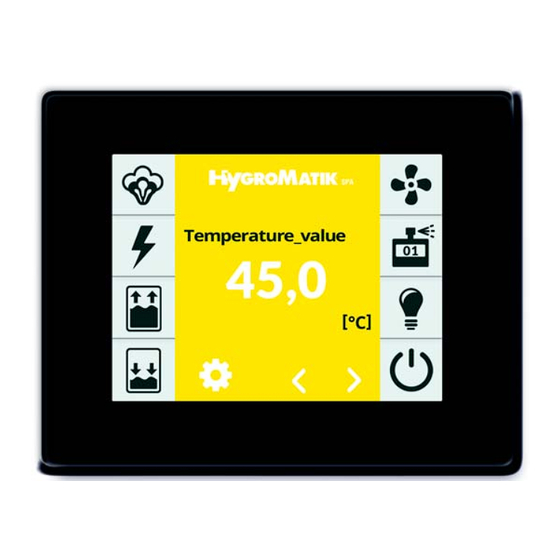
Page 21: The Display
Main display for operating values, navigation using the scroll icons. In the event of a fault or a service message, the HygroMatik logo changes to a display field which describes the fault or the service requirement. Scroll keys, used to display the following operating values: •... - Page 22 Password "010" -> operating functions of operator level (see Section 6.7) In the event of a fault or a service message, the relevant display field is shown instead of the HygroMatik logo. Tapping on it opens the unit info screen (see Sec- tion 6.9).
-
Page 23: Operation Of Control
PLC, using the communication interface. Supplementary documentation is available from HygroMatik for this type of appli- cation. Screen views The operating structure uses several screens, which are schematically displayed in the table below. - Page 24 Overview of the screens Content of screen page Presentation Sec. Screen 1 Used for the basic unit settings (e.g. user language) Commissioning after the unit is switched on for the first time. This page is then closed. To do so, use the confirmation tick to exit it.
-
Page 25: Screen 1 - Commissioning
6.2 Screen 1 - Commissioning » Confirm the input and return to the "Commissioning" screen with the After connection to the mains supply and initial green tick in the top right (cancel by actuation of the control switch, the commis- tapping on "X"... -
Page 26: Control Settings
6.2.3 Control settings a later stage to the parameters listed during commissioning must then be performed at The control behaviour of the control is set in the operator level in the "Settings" and "Con- the next step. The following variants are trol"... - Page 27 Line-up the commissioning parameters No. Parameter Adjustment/value range Meaning/comment Factory presets (FP) bold [ ] explains the term in the glossary [ ] refers to a related term explanation Selection Selection of language 01 Language German Deutsch English English Francais French Castellano...
-
Page 28: Screen 2 - Main Screen
6.3 Screen 2 - Main screen The values for the normal display brightness and the dimmed state can be adjusted by the user, as well as the time after which the main display is dimmed. The main menu of the user level and the operator level (screen 3 „Main menu“) are accessed by tapping on the icon Temp._actual_value... - Page 29 Table of the reading values available in the main display and the set value of the steam bath No. Parameter Adjustment/value range Meaning/comment Factory presets (FP) bold [ ] explains the term in the glossary [ ] refers to a related term explanation Temp._actual_value Reading value The actual value [1] of the steam bath temperature...
-
Page 30: Password Entry
6.4 Password entry The password determines if the main menu Main menu of the user level or the operator level is dis- played. The password codes in use are: Code 000: The main menu of the user level becomes accessible. However, it is sufficient to leave the password prompt with the green tick, without explicitly entering the code. - Page 31 Layout of screen pages The input fields in which changes can be made are shown in italics. Depending on the parame- ter, the input has to be made by: • Selection from predefined offers (multiple choice, see example 1) • Entry of numeric values using an on- screen keyboard (see example 2).
- Page 32 Example 2: Setting the display brightness Tap on "Display lighting_normal" on the screen to call up the input mask: Display lighting_normal Max: 100 The display brightness which is set is dis- played and can be changed using the key- board. Save and return with the green tick, leave the input mask without changes using the "X"...
-
Page 33: Settings Submenu
6.6.1 Settings submenu Table of settings parameters No. Parameter Adjustment/value range Meaning/comment Factory presets (FP) bold [ ] explains the term in the glossary [ ] refers to a related term explanation Language Selection Language selection German Deutsch English English Francais French... -
Page 34: Reading Values Submenu
6.6.2 Reading values submenu Read values table (visible on the user and the operator level) No. Parameter Adjustment/value range Meaning/comment Factory presets (FP) bold [ ] explains the term in the glossary [ ] refers to a related term explanation Operating condition of unit 1 Status_unit 0 Initialization... - Page 35 Continuation of reading value table (1) No. Parameter Adjustment/value range Meaning/comment Factory presets (FP) bold [ ] explains the term in the glossary [ ] refers to a related term explanation 90 Cylinder_full Sensor electrode reports cylinder full status [38] for 60 min (only for ELDB [77]) Value provided by current measurement not plausible (only for ELDB [77]) 91 Current_measurement 92 Main_contactor_current...
- Page 36 Continuation of reading value table (2) No. Parameter Adjustment/value range Meaning/comment Factory presets (FP) bold [ ] explains the term in the glossary [ ] refers to a related term explanation 22 Current_actual_cyl. 1 Reading value The current power consumption of cylinder 1 (only for ELDB [77]) 23 Current_actual_cyl.
-
Page 37: History Submenu
6.6.3 History submenu If an identical fault occurs several times in a row, the first entry relating to this fault is updated with the date of the most recent occurrence and the frequency is incre- mented. A new fault message is not This submenu is identical on the user and the recorded. - Page 38 Continuation of history layout No. Parameter Adjustment/value range Meaning/comment Factory presets (FP) bold 4. Memory entry: Date/time 10 4th fault_entry_date 11 4th fault_entry_message 4. Memory entry: Error message see above 12 4th fault_entry_rate 4. Memory entry: Frequency of occurrence (since initial operation) 13 5th fault_entry_date 5.
-
Page 39: Screen 3 - Main Menu (Operator Level)
6.7 Screen 3 - Main menu (opera- 6.8 Operator level submenus tor level) By tapping on the respective icon, the user accesses the screen page where the param- After the operator level has been selected by eters of the respective group are available for entering the corresponding password (code selection, viewing or for making changes. -
Page 40: Settings Submenu
6.8.1 Settings submenu Table of settings parameters (operator level) No. Parameter Adjustment/value range Meaning/comment Factory presets (FP) bold [ ] explains the term in the glossary [ ] refers to a related term explanation Language Selection Language selection German Deutsch English English... -
Page 41: Reading Values Submenu
6.8.2 Reading values submenu The reading values submenu is no different to that of the user level. The reading values listed in table format in Section 6.6.2 are also available at the operator level. 6.8.3 Control submenu Table of control parameters No. -
Page 42: Service Submenu
6.8.4 Service submenu When the service message was triggered for one of the main contactors, it is advisable to check the meter reading for the remaining 6.8.4.1 Monitoring and service mes- main contactors using the "Kx_switching sages cycles_until msg" (x = 1...5) reading values. The components of the unit which wear due Monitoring to operational reasons, including the steam... - Page 43 Table of service parameters No. Parameter Adjustment/value range Meaning/comment Factory presets (FP) bold [ ] explains the term in the glossary [ ] refers to a related term explanation Steam_amount_service Preset steam volume (see [33]) in kg until service message is triggered. For double cylinder units, this setting applies to both cylinders Reset steam volume counter for cylinder 1 ...
-
Page 44: History Submenu
As a result, the operator can make a change without having to change the param- eters by themselves. The modified parameter set can be provided by HygroMatik. The procedure is as follows: » With the unit switched on, insert the USB stick into the socket on the mainboard. -
Page 45: Blow-Down Submenu
6.8.6 Blow-down submenu Table of blow-down parameters No. Parameter Adjustment/value range Meaning/comment Factory presets (FP) bold [ ] explains the term in the glossary [ ] refers to a related term explanation Correction value for frequency of full blow-down ("+" = more frequently, "-" = less frequently) Full_blow-down_correction ... -
Page 46: Functions Submenu
6.8.8 Functions submenu Table of function parameters No. Parameter Adjustment/value range Meaning/comment Factory presets (FP) bold [ ] explains the term in the glossary [ ] refers to a related term explanation Standby-heating The standby heating [16] keeps the water in the cylinder warm if no demand [5] is present 0 Off Standby heating [16] switched off 1 On... - Page 47 Continuation of function parameters No. Parameter Adjustment/value range Meaning/comment Factory presets (FP) bold [ ] explains the term in the glossary [ ] refers to a related term explanation 16 Assignment_main_relay The relay is energised if ... There is any kind of error Collective_fault Safety_interlock_open The interlock (safety) system [11] is open...
-
Page 48: Communication Interface Submenu
6.8.9 Communication interface sub- menu The communication interface is a serial RS485 computer interface for the remote control of the steam humidifier. With this computer interface, all control operations which can be carried out on the display can also be carried out by the building technology control system, for example. - Page 49 6.8.10 Weekly timer submenu The weekly timer is used to program two switching time ranges per day of the week, each defined by "Start time" and "End time". A set point temperature value and an essence can be assigned to each switching time range.
-
Page 50: Spa Submenu
6.8.11 SPA submenu Table of SPA parameters No. Parameter Adjustment/value range Meaning/comment Factory presets (FP) bold [ ] explains the term in the glossary [ ] refers to a related term explanation 20.0 49.0 Set value [3] of steam bath temperature Temp._set_value 45.0 Temp._set_value... - Page 51 Continuation of SPA parameters No. Parameter Adjustment/value range Meaning/comment Factory presets (FP) bold [ ] explains the term in the glossary [ ] refers to a related term explanation Operating mode of steam bath fan 2 19 Supply_fan2_mode 0 Off 1 On Continuous operation, if unit control switch is in pos.
-
Page 52: Essence Submenu
6.8.12 Essence submenu Table of essence parameters No. Parameter Adjustment/value range Meaning/comment Factory presets (FP) bold [ ] explains the term in the glossary [ ] refers to a related term explanation Selection of essence pump Essences_selection 0 Off No essence 1 Essence 1 Essence pump 1... -
Page 53: Recording Submenu
6.8.13 Recording submenu The status can be checked by calling up the "Saving status" parameter (4). “Enabled" means that the write operation is active. The entire storage can be deleted using the "Delete recording" parameter (5). The control can record 10 data sets internally A data set consists of the following values: on a rolling basis ("Recording"... - Page 54 Table of recording functions No. Parameter Adjustment/value range Meaning/comment Factory presets (FP) bold [ ] explains the term in the glossary [ ] refers to a related term explanation Recording [93] of parameter sets Recording 0 Deactivated No recording 1 Activated Start recording Saving of the existing recording on a USB stick...
-
Page 55: Relay Extension 1 Submenu
6.8.14 Relay extension 1 submenu Relay 5 This icon is only visible in the main menu if relay extension 1 has been enabled in the Relay 6 "Functions" submenu. The assignment of the respective relays and the function definition of the digital input present on the relay board Relay 7 can be made here. -
Page 56: Relay Extension 2 Submenu
6.8.15 Relay extension 2 submenu Relay 8 This icon is only visible in the main menu if relay extension 2 has been enabled in the Relay 9 "Functions" submenu. The assignment of the respective relays and the function definition of the digital input present on the relay board Relay 10 can be made here. - Page 57 After a fault or a service message has occurred, a display which provides informa- tion about the type of message appears in the main display instead of the HygroMatik logo. The content of the messages is described in Section 7.
-
Page 58: Filling_Valve
Entries on the unit info screen No. Parameter Adjustment/value range Meaning/comment Factory presets (FP) bold [ ] explains the term in the glossary [ ] refers to a related term explanation Fault_message_unit Fault messages 0 No_fault No error The plug for the current transformer (ELDB [77]) or the level control (HKDB [78]) is not 1 Plug_ST09 attached 2 Cylinder_extension 1... - Page 59 Entries on the unit info page (ctd.) No. Parameter Meaning/comment Adjustment/value range Factory presets (FP) bold [ ] explains the term in the glossary [ ] refers to a related term explanation Model Reading value Type designation of unit Unit_name Unit 1 Freely selectable text ex-factory.
-
Page 60: Faults And Service Messages
In case of a fault, steam production stops. as well as the unit status. Instead of the HygroMatik logo in the main With most fault messages, one or several display, a display panel appears with a warn- icons also flash, which makes it possible to ing sign, the message "Fault"... -
Page 61: Filling_Valve 1 A. 2
These icons Fault message Possible cause Measure are flashing Filling_valve 1 • Solenoid valve or • Clean water supply Filling_valve 1 a. 2 supply line conta- line and/or solenoid Filling was not successful, minated or defective valve; replace solenoid i.e. the expected level was valve, if defective not achieved after a filling •... -
Page 62: Part._Blow-Down
These icons Fault message Possible cause Measure are flashing Blow-down fault, concern- • Blow-down pump is ing: not driven Part._blow-down - electrical wiring not - Check wiring and re- Full_blow-down o.k. place, if required Blow-down_dilution (only - Mainboard relay is - Measure voltage on ELDB) not energised... - Page 63 These icons Fault message Possible cause Measure are flashing Main_contactor_current • Main contactor con- • Replace main con- (only ELDB) tact sticks tactor A current is measured though the main contactor is not driven. • Main contactor con- • Replace main con- Main_contactor_cyl._full (only ELDB) tact sticks...
- Page 64 These icons Fault message Possible cause Measure are flashing Max.-level (only HKDB) • Excessive air pres- • Reduce air pres- sure in duct has impact sure, check steam Water level has reached its on water in steam cyl- hose for blockages maximum 5x in one single inder via steam hose.
- Page 65 These icons Fault message Possible cause Measure are flashing • Heater element is de- • Measure heater ele- Steam_down_time only fective. ment resistance; re- HKDB) place heater element, The heaters are supplied if required. Nominal re- with current, but water level sistance values are: doesnot change.
- Page 66 These icons Fault message Possible cause Measure are flashing Temp._sensor_miss • Sensor not con- • Check sensor con- No measurements available nected or defective nection, replace sen- sor if required • Connecting line dam- • Check connecting aged line • Input level is defec- •...
-
Page 67: Servicemessages And Warnings
Servicemessages and war- nings Service messages and warnings are shown on the main screen in place of the HygroMa- tik logo, when the cause has occured. When tipping the display field, the unit info screen is shown with the messages in plain text. Mainscreen Message Possible cause... -
Page 68: Functional Fault Chart
7.3 Functional fault chart Possible Possible cause for fault situation Countermeasure condition • Cylinder assembled incorrectly after • Clean cylinder and install it Accumulation of water on the floor maintenance: properly. panel - O-ring damaged, not replaced or - not inserted. - Flange (tongue / groove) damaged. - Page 69 Possible Possible cause for fault situation Countermeasure condition • Unit is operated in "Cylinder full" (for • see fault code 090 The temperature specified is not ELDB only). (Cylinder_full) reached (ctd.) • Incorrect performance design • Check performance data, cabin size and thermal insulation •...
- Page 70 Possible Possible cause for fault situation Countermeasure condition • Cylinder base or blow-down system is • Clean cylinder base or blow- Blow-down pump is working, but no clogged. down system. water is pumped out. • Ventilation hole in elbow is blocked. •...
- Page 71 Possible Possible cause for fault situation Countermeasure condition • • Appearance of Very high conductivity of water resulting Immediately take the unit out lights/lightning in in massive electrode burn-off (indicated of operation, as it could be the cylinder by the brown- black deposits) damaged otherwise.
-
Page 72: Wiring Diagram
8. Wiring diagram Page 72... - Page 73 Page 73...
- Page 74 Page 74...
- Page 75 Page 75...
- Page 76 Page 76...
- Page 77 Page 77...
- Page 78 Page 78...
- Page 79 Page 79...
- Page 80 Page 80...
- Page 81 Page 81...
- Page 82 Page 82...
- Page 83 Page 83...
-
Page 84: Glossary
Coded command, which is, for example, sent from the building control system or a PLC via the Communication interface [13] to the control. The command set available is listed in separate documentation, which is available from HygroMatik on request. Communication interface Serial computer interface for remote control of the unit using, for example, the ... - Page 85 Continuation of glossary (1) Term [Index] Explanation Flushing of dead-end line When this function is activated, the feed water line is flushed during operation phases in which there are no requests in order to prevent germ formation. For this purpose, the inlet solenoid valve and the blow-down pump are activated at the same time.
- Page 86 Continuation of glossary (2) Term [Index] Explanation Second temperature sensor For enhancement of the temperature measurement reliability or the consideration of the influences introduced by on-site particularities, the control may be operated with a 2nd temperature sensor. Prerequisite is the unit's configuration level with an expansion board or a relay board in addition to the mainboard.
- Page 87 Continuation of glossary (3) Term [Index] Explanation Power level If the HKDB [78] is equipped with 3 heaters, the power is provided in 2 levels from a certain performance class onwards. As long as a certain threshold value has not been reached, the heating performance required in level 1 is exclusively provided proportionally via the ...
- Page 88 Unit name Here, "Plant 1" is entered by default. The entry in the field can be changed according to customer requirements using a HygroMatik service tool. Weekly timer The timer makes it possible to program 2 periods per day of the week, each defined by a start time and a end time.
- Page 89 This page intentionally left blank Page 89...
-
Page 90: Technical Data
10. Technical data Page 90... - Page 91 Page 91...
- Page 92 Main display for operating values, navigation using the scroll icons. In the event of a fault or a service message, the HygroMatik logo changes to a display field which describes the fault or the service requirement. Scroll keys, used to display the following operating values: •...
- Page 93 Password "010" -> operating functions of operator level (see Section 6.7) In the event of a fault or a service message, the relevant display field is shown instead of the HygroMatik logo. Tapping on it opens the unit info screen (see Sec- tion 6.9).
- Page 94 A Member of the group 100%...
Need help?
Do you have a question about the FlexLine Spa and is the answer not in the manual?
Questions and answers