Advertisement
Table of Contents
TRADUCTION OF THE ORIGINAL USER'S INSTRUCTIONS
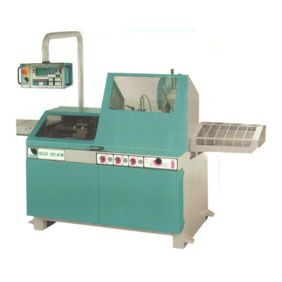
Aluminium cutting circular saw VELOX 350 AF-NC
Automatic Electronic with Numeric Control
VELOX 350AF-NC ED.2011eng rev.00
USER'S INSTRUCTIONS
1/73
IMET Spa
Loc. Tre Fontane - Cisano Bergamasco
Tel. 035/4387911 - Fax. 035/787066
Web site: www.imetsaws.com
E-mail: imet@imetsaws.com
Advertisement
Table of Contents

Summary of Contents for IMET Spa VELOX 350 AF-NC
- Page 1 TRADUCTION OF THE ORIGINAL USER’S INSTRUCTIONS IMET Spa Loc. Tre Fontane - Cisano Bergamasco Tel. 035/4387911 - Fax. 035/787066 Web site: www.imetsaws.com E-mail: imet@imetsaws.com Aluminium cutting circular saw VELOX 350 AF-NC Automatic Electronic with Numeric Control USER’S INSTRUCTIONS VELOX 350AF-NC ED.2011eng rev.00 1/73...
- Page 2 TRADUCTION OF THE ORIGINAL USER’S INSTRUCTIONS We recommend to read carefully the information here included in order to install, use and maintain correctly and safely this machine. Please refer always to this instruction manual in case of assistance service need and keep it carefully for all the machine life.
- Page 3 TRADUCTION OF THE ORIGINAL USER’S INSTRUCTIONS =========================================================================== CE DECLARATION OF CONFORMITY (encl. II A DIR 2006/42/CE) / 03 =========================================================================== THE MANUFACTURER : IMET S.p.A Località Tre Fontane 24034 - CISANO BERGAMASCO –BG- ITALIA HEREBY DECLARES THAT in designing and manufacturing the machine described here below , we have considered the most important requirements of safety and health dictated by the European Directives of the Machine Security.
- Page 4 TRADUCTION OF THE ORIGINAL USER’S INSTRUCTIONS 3 - MACHINE NOISE The decibel pointed out in the workplace in the conditions under described is appointed to the simoultaneous working of some machine parts in motion ( it depends on the detailed cycle ) added to that one of the tool when is cutting the workpiece.
-
Page 5: Guarantee Norms
TRADUCTION OF THE ORIGINAL USER’S INSTRUCTIONS 4 - GUARANTEE NORMS I.ME.T. offers a wide range of sawing machines and accessories, destined to who buys/uses them as part of a commercial or professional activity. The manufacturer grants that this product has been strongly controlled and that there are no defects in the used and working materials for a period of 12 months from the date of the delivery note. -
Page 6: Table Of Contents
TRADUCTION OF THE ORIGINAL USER’S INSTRUCTIONS 5 - SUMMARY pag. 1- PREMESSA 2 – CONFORMITY DECLARATION 3 – AIR NOISE 4 – GUARANTEE NORMS 5 – Index 6 – Technical characteristics 7 – Installation – minimum requirements 8 – Moving and transit 9 –... -
Page 7: Technical Characteristics
TRADUCTION OF THE ORIGINAL USER’S INSTRUCTIONS TECHNICAL CHARACTERISTICS - Automatic CNC circular saw suited to cut aluminium and light metals solid and profiles with high accuracy. Possibility to set the machine for brass and copper profiles by 2 speed motor. Mitre cutting from 0°... - Page 8 TRADUCTION OF THE ORIGINAL USER’S INSTRUCTIONS 7 - INSTALLATION The machine can work according to the parameters provided by the manufacturer if it is rightly installed and the minimum requirements are observed, as follows : - Machine must be used indoor and with temperatures from +5 to + 40 ° C. - The relative humidity of the environment must not go over 95%.
- Page 9 TRADUCTION OF THE ORIGINAL USER’S INSTRUCTIONS N.B. All the VELOX models are already supplied with a conveyor that during the cutting catches a considerable quantity of chips / powders made by the cutting. The tool ventilation effect is agreed with the air flow direction that a suction plant (supplied as optional, for the models VELOX only) can produce.
- Page 10 TRADUCTION OF THE ORIGINAL USER’S INSTRUCTIONS When choosing and then using equipment such as ropes, chains or lifting belts, be careful about their geometry during the lifting and about the consequent actual loading capacity. The machine is structured so as to offer lifting points, which are appropriately indicated and will have to be used for lifting it.
-
Page 11: Blade Choice
TRADUCTION OF THE ORIGINAL USER’S INSTRUCTIONS nearest to the feeder. For the longest workpieces fix the floor stand to the floor . Rollers are in plastic material to avoid light metal or painted profiles damages. The beginning connection to the machine (see below) is 1 m. long and it is already provided with pedestal; pay attention to not damage the END OF BAR electric microswitch when you are installing it (left picture).It can be completed with 2 meters each roller table. - Page 12 TRADUCTION OF THE ORIGINAL USER’S INSTRUCTIONS For making a right cut it is also necessary to establish the pitch ( t ) or the suitable number of teeth ( z ). The blade must generally have the toothing as follows: - close toothing for cutting thin materials, tubular and profiles (for example 108 or 96 teeth with a negative inclination for reducing the noise too !;) - thin toothing for cutting solid materials or pieces that need a long piece of blade (for example 72 or 84 teeths with...
- Page 13 TRADUCTION OF THE ORIGINAL USER’S INSTRUCTIONS 11. INSTRUCTIONS FOR USE AND WARNINGS This machine can make automatic and semiautomatic work cycles, however at the end of each one the operator has to remove the material that has been cut and possibly change the cutting conditions. Therefore the saw sometimes must be manually adjusted and then it works in semiautomatic cycle (so the operator is not indispensable).
- Page 14 TRADUCTION OF THE ORIGINAL USER’S INSTRUCTIONS On some parts of the machine there are some stickers which warn about the safety measures that have to be taken by the operator who runs it. Their meaning (easy to understand) is indicated in the following chart VELOX 350AF-NC ED.2011eng rev.00 14/73...
- Page 15 TRADUCTION OF THE ORIGINAL USER’S INSTRUCTIONS 11.2 - OPERATOR’S SAFETY This section illustrates the safety protections applied on the saw, according to the current legislation in the field of safety. 11.2.1. ELECTRIC EQUIPMENT – Norm EN 60204-01 . Electric board closed with screws - general switch .
-
Page 16: Machine Description
TRADUCTION OF THE ORIGINAL USER’S INSTRUCTIONS 112.2 – PROTECTION AGAINST ACCIDENTAL CONTACTS . Complete metallic protection of the blade and the blade shaft. It is comprised of the metal chips conveyor on the back side of machine. . Rotating metallic moving guard, fixed to the main blade guard. It assures the coverage of the blade in every position, except for the stretch of blade which makes the cut. - Page 17 TRADUCTION OF THE ORIGINAL USER’S INSTRUCTIONS It is not suitable to cut wood and assimilated materials (cfr. D.M. 2006/42/EEC, enclosure I, paragraph 2.3). The automatic working consists usually of: locking of the material, feeding and cutting, tool return and feeding for a new cut..
- Page 18 TRADUCTION OF THE ORIGINAL USER’S INSTRUCTIONS VELOX 350AF-NC ED.2011eng rev.00 18/73...
-
Page 19: Moving And Transit
TRADUCTION OF THE ORIGINAL USER’S INSTRUCTIONS Place the bracket inside the floor stand. For opening the doors you have to loosen the lower hooks indicated in the picture- pos. 1 - dr. RI0503-. Remove the protective substances placed on the surfaces during the moving and transit by using cleaned and non-filamentous clorth or paper, and please check that there is no rust on the metallic parts. - Page 20 TRADUCTION OF THE ORIGINAL USER’S INSTRUCTIONS WARNING : For safety reason each time you re-connect the supply line to the machine , AT THE FIRST INSTALLATION , in case you change the supply wall socket take out the blade and the flanges - pos. 1, 2, 3, 4, 5 /dr.
-
Page 21: Blade Mounting
TRADUCTION OF THE ORIGINAL USER’S INSTRUCTIONS In case the SPINDLE is rotating in the opposite direction, turn the machine off by pushing the general switch - pos.2/dr. RI0346 -, disconnect the line plug, change the connection of two of the wires of the line connection, except for the green / yellow grounding cable and start again from point b). -
Page 22: Regulations
TRADUCTION OF THE ORIGINAL USER’S INSTRUCTIONS 15 – CONTROL DESCRIPTION The numeric control here installed is descripted in the enclosed manual , the cicle and functions are standard as following description The sectionalising devices of energies are : On the left side of the rear control box there is the main switch with interlocking attachment, -pos.2/RI0346-, at the back of the base, right side there is the air connection-pos.5/dr.RI0344- for the pneumatic plant. - Page 23 TRADUCTION OF THE ORIGINAL USER’S INSTRUCTIONS New control keyboard - MAHLER – for VELOX 350 AF-NC and SIRIO 370 AF-NC saws machine VELOX 350AF-NC ED.2011eng rev.00 23/73...
- Page 24 TRADUCTION OF THE ORIGINAL USER’S INSTRUCTIONS This panel shows some buttons that are not in use on these machine, and others that can cause misunderstanding about their function. Here are resumed 1 = direction arrows, to change page or scroll text in the HELP section –see below 2= RUN to start the selected program 3= PGM edits the contents of the selected program 4= DIR goes directly to the program library...
- Page 25 TRADUCTION OF THE ORIGINAL USER’S INSTRUCTIONS 15.1 - Machine functions- Description of working cycle ,With air and electric supply connected Push black button on disconnect switch (see above) on side of machine. The first display you will see is shown to the right. Overview of Controls The group on the Right side are as follows: Sawvice clamp...
- Page 26 TRADUCTION OF THE ORIGINAL USER’S INSTRUCTIONS Coolant Controls / Chip suction plant controls Setting Material Height: By the pneumatic air nozzle device your machine has -Push Raise button until sawframe is at desired height been factory preset that the coolant will automatically for material to be cut (about 10 mm over it) come on during a sawing cycle, and automatically shut -Push &...
- Page 27 TRADUCTION OF THE ORIGINAL USER’S INSTRUCTIONS Calibrating feeder vice must be done under the following circumstances: 1. When you first receive machine, prior to operating automatically 2. When the power has been removed from machine, that is each working day. 3.
- Page 28 TRADUCTION OF THE ORIGINAL USER’S INSTRUCTIONS F5 - move to the beginning of list You may do this only when in the program mode (PGM) which is identified as in the previous photo with only a single page shown in upper left hand corner. The curser is the thin horizontal line that can be moved by the 4 red arrow of the pushbutton section.
- Page 29 TRADUCTION OF THE ORIGINAL USER’S INSTRUCTIONS Note: After you enter RUN you will see the symbol of 4 arrows in the upper left hand corner that indicates ready Viewing Progress of your Job for fully automatic aperation, and it will not be possible to During the course of automatic operation you will see the enter any more data without going back to previous information shown at right.
- Page 30 TRADUCTION OF THE ORIGINAL USER’S INSTRUCTIONS In the example, stars have been cleared from lines 3 & -Enter length desired on keypad 4, so if you run this program now, only jobs 3 & 4 will run -Push (start) -Feeder vice will automatically move, clamp your material, advance to the correct length, and clamp.
- Page 31 TRADUCTION OF THE ORIGINAL USER’S INSTRUCTIONS Changing of Lenght tolerance To increase/decrease the feeder positioning tolerance , from first page: push: F1 , F3 , F2 , password 123456, F6 , F6 (over this button appairs AX1/A ), Choice it by pushing F1 , scroll to the line 8 =Q.
- Page 32 Page -15.2- PREPARATION FOR THE SEMIAUTOMATIC CYCLE (one cut) Put the work piece you have to cut in the vice, close manually the jaws and open them of an half turn, by leaving 3/4 mm between the piece and the jaws necessary for a better using of automatic closing, and place it a little back from the cutting line.
- Page 33 Page If you don’t use 350 mm diameter blade you have to change the position of the safety screw of downfeed stroke ( it assure that the blade can’t cut the machine base). The screw is fixed near the lowering pin-; look for it and move it if your blade is less 350 mm dia. Take in accout the blade cover cannot moves completely aroun the blade in these case.
- Page 34 Page 15.7 - PREPARATION TO THE AUTOMATIC CYCLE You can make automatic cuts (by setting the number of pieces and of repetitions of feeder strokes) only after have been managed for a job program ; referring to picture RI0502: 1 - Open completely the feeder guard , position the front feeder jaw - pos. 5 /dr. RIO346 - leaving a total gap of 2-3 mm. between the workpiece and the vice.
- Page 35 Page • Move the advancer carriage towards the blade (forwards) with button (20) and when it has arrived near the base (completely forward) turn back by about 20 or 30 mm with the button (21). • Push the button "F1" [ SET ] then "F1" [set-point icon] then "F4" [ axis 1 set-point ] and confirm the axis zero-adjustment request with start key [ I ] (pos.8).
- Page 36 Page • values) • Vel1= speed of the feeder during automatic cycle. • 1 slow, • 2 medium. • 3 high • • NOTE that by keeply pushed HELP button you can read informations on each figure or data screen •...
- Page 37 Page upper corner- to select it . The display shows again the program, • • • • 70.0% = is the percentile position of the start of • you push the start button [ I ] at the left side , the cut , that is the start cutting position: normally is then you are asked for the trim cut [F1] or not [ F2 ].
-
Page 38: Functioning
16.5 - The model VELOX 350 AF-NC can be equipped (optional on request) with prolonged jaws, that allow to have a very shot scrap end ( 230 mm ab.) at the end of the bar, even though they reduce the maximum cutting capacities of 30 mm width and don’t allows to use the upper roller. - Page 39 TRADUCTION OF THE ORIGINAL USER’S INSTRUCTIONS VICES - dr. RI0088 - The shaped jaws in aluminium - pos. 1, 2, 3, 4 - (available on some models) can be adjusted in the height in order to be suitable to the profiles that must be cut. On the cutting position at 0 degrees it is possible to mount the back jaws upside down - pos.
-
Page 40: Maintenance - For The User
TRADUCTION OF THE ORIGINAL USER’S INSTRUCTIONS by machine still connected get down the cutting unit by pushing “HEAD DOWN” till the blade reaches the lowest point, take away the back cylinder stem by taking out the screw of the articulating joint, then put the stem inside by pushing “HEAD UP”... -
Page 41: Machine Running-In
TRADUCTION OF THE ORIGINAL USER’S INSTRUCTIONS REPLACE THE WORN OUT BELTS IN TIME. 18 - - BLADE RUNNING-IN To grant a better performance of the machine and a longer blade life a good running-in is essential. For the first operation we recommend reducing the blade penetration speed into the workpiece to half of the normal value and keeping the blade rotation speed constant. -
Page 42: Draining Of Used/Produced Substances
TRADUCTION OF THE ORIGINAL USER’S INSTRUCTIONS 20 - DRAINING OF USED / PRODUCED SUBSTANCES Please remember to abide by the current Law Norms concerning the draining of: - materials used by the machine (for example hydraulic circuit oil, reduction gear oil, oil for installations of lubrication and so on);... -
Page 43: Machine Demolition
TRADUCTION OF THE ORIGINAL USER’S INSTRUCTIONS 13 = Burnt or demaged motor 14 = Electric feeding is not right 15 = Transmission blocked between blade and blade spindle. Damaged or worn out belt 16 = Teeth pitch of the blade 17 = Teeth form of the blade 18 = Used blade or missing teeth 19 = Cutting speed not right... -
Page 44: Spare Parts
TRADUCTION OF THE ORIGINAL USER’S INSTRUCTIONS Generally: you must empty the cooling installation tank, take out the oil from the reduction box, from the hydraulic or hydropneumatic installation. Lock the parts that could move and cause danger or instability. Remove the parts assigned to the differentiated draining, for example the printed circuit, display stations, programming keyboards, buffer batteries and so on, especially the ones which shows the picture ..In these cases, in relation with the WEEE/AEEE Regulations ask to the supplier to know the right process, that depends by the machine... - Page 45 TRADUCTION OF THE ORIGINAL USER’S INSTRUCTIONS 17.2 OILS AND LUBRICANTS (Comparation table marked RI0108): VELOX 350 +SIRIO 370AF-NC FAST INSTRUCTIONS...
-
Page 46: Maintenance - For Qualified Technicians
TRADUCTION OF THE ORIGINAL USER’S INSTRUCTIONS 24 - MAINTENANCE - for qualified technicians --------------------------------------------------------------------------------------------------------------------------------------------- IMPORTANT ----------------------------------------------------------------------------------------------------------------------------------------------- If you want to make some special maintenance/disassembly/resetting operations on the machine, it is necessary to know all information for working in safe conditions. And then the knowledge of the interventation techniques, proper of the qualified technicians, allow to solve easier all problems found by the user during the machine’s life. - Page 47 TRADUCTION OF THE ORIGINAL USER’S INSTRUCTIONS VELOX 350 +SIRIO 370AF-NC FAST INSTRUCTIONS...
- Page 48 TRADUCTION OF THE ORIGINAL USER’S INSTRUCTIONS VELOX 350 +SIRIO 370AF-NC FAST INSTRUCTIONS...
- Page 49 TRADUCTION OF THE ORIGINAL USER’S INSTRUCTIONS VELOX 350 +SIRIO 370AF-NC FAST INSTRUCTIONS...
- Page 50 TRADUCTION OF THE ORIGINAL USER’S INSTRUCTIONS VELOX 350 +SIRIO 370AF-NC FAST INSTRUCTIONS...
- Page 51 TRADUCTION OF THE ORIGINAL USER’S INSTRUCTIONS VELOX 350 +SIRIO 370AF-NC FAST INSTRUCTIONS...
- Page 52 TRADUCTION OF THE ORIGINAL USER’S INSTRUCTIONS VELOX 350 +SIRIO 370AF-NC FAST INSTRUCTIONS...
- Page 53 TRADUCTION OF THE ORIGINAL USER’S INSTRUCTIONS XXXXXXXXXXXXXXXXXXXXXXXXX VELOX 350 +SIRIO 370AF-NC FAST INSTRUCTIONS...
- Page 54 TRADUCTION OF THE ORIGINAL USER’S INSTRUCTIONS XXXXXXXXXXXXXXXXXXXXXXXXXXX VELOX 350 +SIRIO 370AF-NC FAST INSTRUCTIONS...
- Page 55 TRADUCTION OF THE ORIGINAL USER’S INSTRUCTIONS VELOX 350 +SIRIO 370AF-NC FAST INSTRUCTIONS...
- Page 56 TRADUCTION OF THE ORIGINAL USER’S INSTRUCTIONS VELOX 350 +SIRIO 370AF-NC FAST INSTRUCTIONS...
- Page 57 TRADUCTION OF THE ORIGINAL USER’S INSTRUCTIONS VELOX 350 +SIRIO 370AF-NC FAST INSTRUCTIONS...
- Page 58 TRADUCTION OF THE ORIGINAL USER’S INSTRUCTIONS VELOX 350 +SIRIO 370AF-NC FAST INSTRUCTIONS...
- Page 59 TRADUCTION OF THE ORIGINAL USER’S INSTRUCTIONS VELOX 350 +SIRIO 370AF-NC FAST INSTRUCTIONS...
- Page 60 TRADUCTION OF THE ORIGINAL USER’S INSTRUCTIONS VELOX 350 +SIRIO 370AF-NC FAST INSTRUCTIONS...
- Page 61 TRADUCTION OF THE ORIGINAL USER’S INSTRUCTIONS VELOX 350 +SIRIO 370AF-NC FAST INSTRUCTIONS...
- Page 62 TRADUCTION OF THE ORIGINAL USER’S INSTRUCTIONS VELOX 350 +SIRIO 370AF-NC FAST INSTRUCTIONS...
- Page 63 TRADUCTION OF THE ORIGINAL USER’S INSTRUCTIONS VELOX 350 +SIRIO 370AF-NC FAST INSTRUCTIONS...
- Page 64 TRADUCTION OF THE ORIGINAL USER’S INSTRUCTIONS VELOX 350 +SIRIO 370AF-NC FAST INSTRUCTIONS...
- Page 65 TRADUCTION OF THE ORIGINAL USER’S INSTRUCTIONS VELOX 350 +SIRIO 370AF-NC FAST INSTRUCTIONS...
- Page 66 TRADUCTION OF THE ORIGINAL USER’S INSTRUCTIONS VELOX 350 +SIRIO 370AF-NC FAST INSTRUCTIONS...
- Page 67 Page • FAST INSTRUCTION FOR USE AUTOMATIC MACHINE VELOX & SIRIO 370 AF-NC • Put the machine onto the floor and tip it to about 2 mm/m on the right side (piece unload) to empty out the cooling liquid that will be found on the material to be cut. Connect the machine to power supply network, air and electricity with neutral wire..
- Page 68 Page • push "Enter", key in the quantity, • • • • 003 =field where you can create the identification name • • push "Enter", key in the length of possible other pieces to be cut and their quantity • •...
- Page 69 Page • • • • • 70.0% = is the percentile position of the start of • ON/FF = on this machine is not in use D = on this the cut , that is the start cutting position: normally is machine is not in use about 8/10 mm over the piece surface.
- Page 70 Page • The display shows again the program, • The machine carries out the program right until you push the start button [ I ] at the left side , then the end. If it stops because there is no more you are asked for the trim cut [F1] or not [ F2 ].
- Page 71 Page • VELOX 350AF-NC ED.2008 rev.00 8/73...
- Page 72 Page • -New control panel –MAHLER- for circular sawing machines SIRIO 370 AF-NC- VELOX 350 AF-NC • This panel shows some buttons that are not in use on these machine, and others that can cause misunderstanding about their function. Here are resumed: •...
- Page 73 Page VELOX 350AF-NC ED.2008 rev.00 10/73...
Need help?
Do you have a question about the VELOX 350 AF-NC and is the answer not in the manual?
Questions and answers