Table of Contents
Advertisement
Quick Links
Acumen Electronics Ltd
15 Glenmore Bus Pk
Colebrook Way
Andover
Hants
SP10 3GQ
UK
Tel; +44 (0)1264 359922
Fax; +44 (0)1264 359933
www.acumen-electronics.co.uk
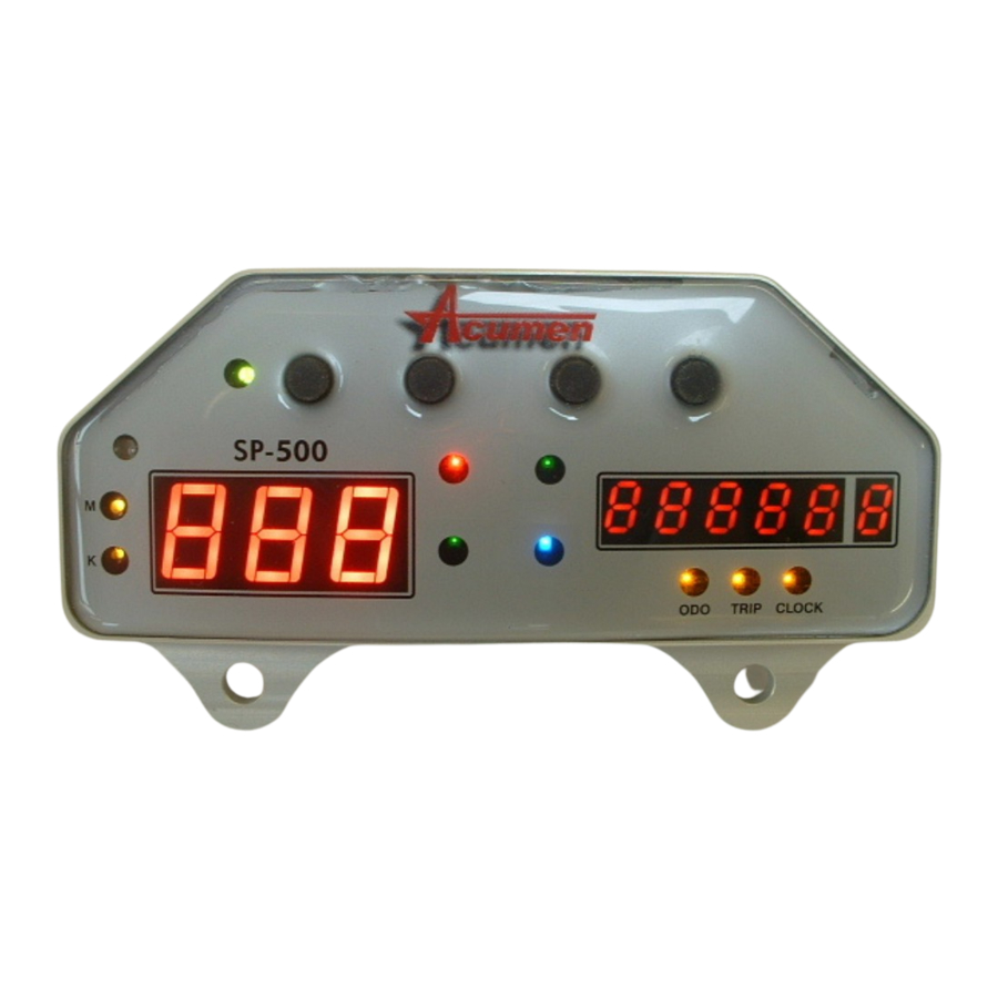
Acumen SP500 Universal Speedo
The speedometer is designed as a universal fit.
You will need to perform some slight assembly on it, to suit your own individual requirements.
The Acumen Universal Speedometer consists of;
1. A Speedometer head sub-assembly. – without fascia
2. Electronic pick-up for the speedometer
3. Fitting and Literature kit.
Fitting instructions
Speedometer
The SP500 speedometer has 5 warning lights built into the system. These are all white LED's so you can
identify the LED's with the coloured icons provided. The Icons are EC standard icons.
Of the 5 Indicator LED's, two need to be switched to ground (earth) to illuminate – such as for oil
pressure or Neutral light, and three need to be switched to 12V to illuminate – such as for indicators, main
beam or lights-on.
The drawing below will indicate how the warning lights are switched.
NOTE. Acumen recommend you use one of the LED lights as a 'lights-on' indication. As the
Speedometer is permanently illuminated, there is no 'lights-on' indication.
Some countries may require to use such an indicator if the motorcycle lights can be switched off and on.
Page 1
Advertisement
Table of Contents

Summary of Contents for Acumen SP500
- Page 1 Fitting instructions Speedometer The SP500 speedometer has 5 warning lights built into the system. These are all white LED’s so you can identify the LED’s with the coloured icons provided. The Icons are EC standard icons. Of the 5 Indicator LED’s, two need to be switched to ground (earth) to illuminate – such as for oil pressure or Neutral light, and three need to be switched to 12V to illuminate –...
- Page 2 These indicators switch to 12V to make them illuminate When you have decided which indicator does what, use the pre-coloured icons to indicate the purpose of the indicator. Cut the icon from the sheet and place it on the fascia – by carefully removing the fascia from the Acetate sheet –...
- Page 3 Special Version. Either version will need some filtration added to enhance the contrast and, therefore, the ‘viewability’ of the display. Acumen has included a selection of filters in the kit for this purpose. We recommend you try the filters before adding the fascia – then cut the chosen filter to slightly larger than the chosen display window and stick to the fascia.
-
Page 4: Electrical Connections
NOTE! If you are using one 12V switched for both the left and right m/c indicator lights you will need to fit two diodes in the circuit thus; Diodes are available from Acumen Electronics Free of Charge on Request – or from any Electronics stockist. - Page 5 Calibrating the Speedo to your motorcycle – The speedo needs to let you know, accurately, what speed you are doing and what distance you have done. You therefore need to enter a calibration code. To do this, look at the attached chart which will give you a code dependent upon the tyre size that the speedo reader head is mounted on.
- Page 6 Speedo Calibration Code Speedo Tyre Calibration Type Size Code 15” Road 140/90 150/90 170/80 200/70 16” Road 350-16 500-16 100/80 100/90 110/90 120/80 120/80 130/70 130/90 140/80 140/90 150/80 160/80 180/60 200/60 MT90B16 MT90-16 17” Road 325-17 350-17 110/70 110/80 120/60 120/70 130/70...
Need help?
Do you have a question about the SP500 and is the answer not in the manual?
Questions and answers