Table of Contents
Advertisement
Quick Links
Advertisement
Table of Contents
Troubleshooting

Related Manuals for Raymarine GVM400


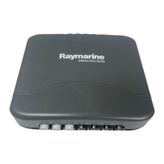
Summary of Contents for Raymarine GVM400
- Page 1 GVM400 video module Installation instructions...
- Page 3 , SeaTalk and Sportpilot are registered trademarks of Raymarine UK Limited. RayTalk, Seahawk, Smartpilot, Pathfinder and Raymarine are registered trademarks of Raymarine Holdings Limited. FLIR is a registered trademark of FLIR Systems, Inc. and/or its subsidiaries. All other trademarks, trade names, or company names referenced herein are used for identification only and are the property of their respective owners.
-
Page 5: Table Of Contents
6.1 Technical specification..........30 Suppression ferrites ............8 Chapter 7 Spare parts ..........31 Connections to other equipment ........8 7.1 GVM400 video module spares ........32 Product disposal ............. 8 IMO and SOLAS............. 8 Technical accuracy ............8 G-Series handbooks ............9 Chapter 2 Planning the installation ...... - Page 6 GVM400 Installation instructions...
-
Page 7: Chapter 1 Important Information
This product contains high voltages. Do NOT remove any covers or otherwise attempt to access internal • Raymarine equipment and cables connected to it are: components, unless specifically instructed in this document. – At least 1 m (3 ft) from any equipment transmitting or cables carrying radio signals e.g. -
Page 8: Suppression Ferrites
Directive requires the recycling of waste electrical and electronic equipment. Whilst the WEEE Directive does not apply to some Raymarine products, we support its policy and ask you to be aware of how to dispose of this product. Suppression ferrites Raymarine cables may be fitted with suppression ferrites. -
Page 9: G-Series Handbooks
G-Series system user reference 81276 handbook Glass Bridge monitors user guide 81324 81316 G-Series compact keyboard G-Series command center keyboard 87084 Additional handbooks Description Part number SeaTalk reference manual 81300 All documents are available to download as PDFs from www.raymarine.com. Important information... - Page 10 GVM400 Installation instructions...
-
Page 11: Chapter 2 Planning The Installation
Chapter 2: Planning the installation Chapter contents • 2.1 Parts supplied on page 12 • 2.2 Power cables on page 12 • 2.3 Entertainment system example on page 13 • 2.4 Dimensions on page 15 Planning the installation... -
Page 12: Parts Supplied
24 volts 0.52 12 volts 0.82 15 to 20 m (49.2 to 65.6 ft) 24 volts 0.52 1. GVM400 video module. 2. Installation instructions. 3. 1.5 m (4.9 ft) S-Video cable. 4. 1.5 m (4.9 ft) Audio cable. GVM400 Installation instructions... -
Page 13: Entertainment System Example
2.3 Entertainment system example Audio S-Video JK L PAGE WPTS MENU ENTER RANGE PQRS WXY Z ACTIVE DAT A DODGE ST ANDBY PIL OT CANCEL DVI / VGA SeaT alk Audio SeaTalk SeaTalk S-Video D11795-1 Planning the installation... - Page 14 4. Satellite TV. 5. Wireless base station. 6. Video camera. 7. Video camera with audio connection. 8. GVM video module. 9. SeaTalk switch. 10. GPM processor unit. 11. Audio output (to vessel’s audio system). 12. SeaTalk backbone. GVM400 Installation instructions...
-
Page 15: Dimensions
2.4 Dimensions 56 mm (2.2 in) 237 mm (9.33 in) Planning the installation... - Page 16 GVM400 Installation instructions...
-
Page 17: Chapter 3 Cables And Connections
Chapter 3: Cables and connections Chapter contents • 3.1 GVM video module connections on page 18 • 3.2 Thermal camera connection on page 20 Cables and connections... -
Page 18: Gvm Video Module Connections
3.1 GVM video module connections SeaT alk D11820-1 GVM400 Installation instructions... - Page 19 8. Illustration showing the labels for the video and audio connections on the GVM video module. Note: Each GVM400 video module supports 1 S-Video input, or 4 composite video inputs (reduced to 3 composite video inputs if using S-Video input). If a thermal camera is connected to a GVM video module no further video devices may be connected to that GVM unit.
-
Page 20: Thermal Camera Connection
Joystick Control Unit (JCU) with the camera this must also be connected to the SeaTalk switch. A composite video connection is also required between the camera and a GVM video module. SeaT alk D11935-1 1. GPM processor unit. 2. SeaTalk switch. GVM400 Installation instructions... - Page 21 3. PoE (Power over Ethernet) injector (only required if using the dealer or the Raymarine website (www.raymarine.com) for latest optional JCU). software versions. • For further information regarding the camera’s installation 4. Joystick Control Unit (JCU), optional. (including connections and mounting), refer to the installation 5.
- Page 22 Note: You can only connect 1 thermal camera to each GVM video module in your G-Series system. When a thermal camera is connected, each GVM video module is limited to that input only and does NOT support the connection of any further video devices. GVM400 Installation instructions...
-
Page 23: Chapter 4 Location And Mounting
Chapter 4: Location and mounting Chapter contents • 4.1 Location requirements on page 24 • 4.2 Mounting arrangement on page 24 Location and mounting... -
Page 24: Location Requirements
• Do NOT install near sources of heat or vibration (for example, an engine). • Install below decks in a dry area. • Must be mounted on a vertical surface. Sides and top must be level. GVM400 Installation instructions... -
Page 25: Chapter 5 Troubleshooting
Chapter 5: Troubleshooting Chapter contents • 5.1 Video troubleshooting on page 26 Troubleshooting... -
Page 26: Video Troubleshooting
Check that SeaTalk cables are free from damage. Software mismatch between equipment Contact Raymarine technical support. may prevent communication. Only Video Input 1 on the GVM video The GVM video module has been If you no longer want to connect a thermal camera to the GVM video module module is working. - Page 27 LED state Possible causes 4 flashing red LEDs. Flash write error. Video stopped. 6 flashing red LEDs. 7 flashing red LEDs. Video error. 8 flashing red LEDs, possibly followed Hardware read failure. by flashing amber. Troubleshooting...
- Page 28 GVM400 Installation instructions...
-
Page 29: Chapter 6 Technical Specification
Chapter 6: Technical specification Chapter contents • 6.1 Technical specification on page 30 Technical specification... -
Page 30: Technical Specification
• Operating temperature: -15 ºC to 92/31/EEC +55 ºC (5 ºF to 131 ºF) • EN60945:2002 • Non-operating temperature: -25 ºC to +70 ºC (–13 ºF to 158 ºF) • Relative humidity limit: 80% • Water protection: drip resistant when mounted vertically. GVM400 Installation instructions... -
Page 31: Chapter 7 Spare Parts
Chapter 7: Spare parts Chapter contents • 7.1 GVM400 video module spares on page 32 Spare parts... -
Page 32: Gvm400 Video Module Spares
7.1 GVM400 video module spares The following parts are available as spares: Cable Part number Notes GVM Connector Cover R08276 GVM install pack R08318 GVM400 Installation instructions... - Page 34 www.ra ym a rin e .c o m...
Need help?
Do you have a question about the GVM400 and is the answer not in the manual?
Questions and answers