Table of Contents
Advertisement
Quick Links
Advertisement
Table of Contents

Related Manuals for GHI electronics EMX


Summary of Contents for GHI electronics EMX
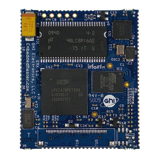
- Page 1 December 16, 2014 User Manual EMX Module Top EMX Module Bottom Document Information Information Description Abstract This document covers information about the EMX Module, specifications, tutorials and references. G H I E l e c t r o n i c s...
- Page 2 GHI Electronics,LLC EMX SoM User Manual Revision History Rev No. Date Modification Rev. 0.02 12/16/14 Misc typos, etc. Rev. 0.01 8/27/14 Preliminary version Rev. 0.02 Page 2 of 69 www.GHIElectronics.com...
-
Page 3: Table Of Contents
3.1.Pin-out Table................8 7.15.USB Host.................50 4.EMX on boot up................13 7.16.Accessing Files and Folders...........51 4.1.Boot Mode Pins..............13 SD/MMC Memory..............53 4.2.GHI Boot Loader vs. TinyBooter vs. EMX Firmware USB Mass Storage............53 (NETMF/TinyCLR)..............15 7.17.Secure Networking (TCP/IP)...........53 4.3.The Loader and Firmware Debug Access Interface..15 The Extensions..............53 5.The GHI Boot Loader..............16... -
Page 4: Introduction
With just power and some connectors, developers can utilize the EMX Module to bring the latest technologies to any products. There are no additional licensing or fees and all the development tools and SDKs are provided freely. -
Page 5: Ghi Electronics And Netmf
EMX Module firmware, to provide regular and free releases. Users can simply load the new software on the EMX Module using USB or Serial, and even use the in-field-update feature. This feature allows the upgrade to be done through any of the available interface, including file system and networking. -
Page 6: Emx Module Key Features
GHI Electronics,LLC EMX SoM User Manual Introduction 1.3. EMX Module Key Features .NET Micro Framework TCP/IP Stack (.NET sockets) ● ● 72 Mhz 32-bit ARM7 SSL secure networking ● ● 16 MB RAM WiFi ● ● 4.5 MB FLASH ●... -
Page 7: The Hardware
.NET Micro Framework core very efficiently. Also, the processor includes an RTC that can operate while while the processor is off. The EMX Module already has the needed circuitry to run the RTC. Users only need to add a battery or a super capacitor to VBAT pin. -
Page 8: Pin-Out Description
Advanced details on all pins can be found in the LPC2478 datasheet ● Most signals on EMX are multiplexed to offer more than one function for every pin. It is up to the developer to select which one of the functions to use. GHI drivers and .NET Micro Framework does checking to make sure the user is not trying to use two functions on the same pin. - Page 9 GHI Electronics,LLC EMX SoM User Manual Pin-Out Description LPC2478 EMX IO 2 Feature EMX Module H/W Name Pin Description 3.3V Connect to 3.3 volt source. P0.25 IO6* ADC2/ ADC2 (10Bit Analog to Digital Input) COM4 or Serial port (UART) TXD transmit signal (Out) for COM4.
- Page 10 GHI Electronics,LLC EMX SoM User Manual Pin-Out Description LPC2478 EMX IO 2 Feature EMX Module H/W Name Pin Description 3.3V Connect to 3.3 volt source. Not Connected. P3.26 IO49 PWM3 PWM3 (Pulse Width Modulation Output) LPC2478 PWM Timer 1. P3.17...
- Page 11 The alarm pin is an RTC controlled output. This is a 1.8 V pin. P3.23 IO71 LMODE General purpose digital I/O is used to choose the access interface for EMX between USB (Low) or COM1(High or not connected) on startup (refer to EMX access interface section). P2.23 IO72* T_X_Right Touch Screen X-axis Right digital output signal.
- Page 12 GHI Electronics,LLC EMX SoM User Manual Pin-Out Description LPC2478 EMX IO 2 Feature EMX Module H/W Name Pin Description 3.3V Connect to 3.3 volt source. JTAG TDO JTAG TDO signal. JTAG TRST JTAG TRST signal. JTAG RTCK JTAG RTCK signal.
-
Page 13: Emx On Boot Up
EMX SoM User Manual EMX on boot up 4. EMX On Boot Up Software run on the EMX Module is divided into different components: The GHI Boot loader – initializes memories and executes TinyBooter. It is also used to ●... - Page 14 Low? And 53 High? or MFDeploy. Valid EMX firmware (TinyCLR?) Access EMX firmware Stay in EMX firmware and wait for an action through Visual C# or other Valid application code? deployment and/or control tool. Application loader and debugger level. Execute application program...
-
Page 15: Ghi Boot Loader Vs. Tinybooter Vs. Emx Firmware (Netmf/Tinyclr)
4.3. The Loader and Firmware Debug Access Interface The communication between a PC and the EMX Module can be done using a USB port or a serial port (COM1). This interface can be used for updating, deploying or debugging the software components. -
Page 16: The Ghi Boot Loader
The GHI Boot Loader 5. The GHI Boot Loader The EMX Boot Loader software is pre-loaded and locked on the EMX Module. It is used to update TinyBooter and can be used to do a complete erase all flash memory. The GHI boot loader is rarely needed but it is recommended to keep access available in all project designs. -
Page 17: Updating Tinybooter Using Fez Config
The following procedures' images are from version 2.0.2.0 of FEZ Config running on Windows 8.01. The images may vary with other versions. The first step is to interface the EMX with the PC. This is best done using the USB pins, and the appropriate cable. -
Page 18: Updating Emx Manually
GHI Electronics,LLC EMX SoM User Manual The GHI Boot Loader NOTE: When finished updating tinyBooter, FEZ Config will automatically update TinyCLR as needed. Updating EMX Manually FEZ Config is the recommended tool for updating TinyBooter on the module. This section describes a manual process. - Page 19 Instructions for updating TinyBooter (commands to the GHI Boot loader are case sensitive): 1. Boot the EMX using the Pin configuration described in the Boot Mode Pins section to start the Boot loader's command/control interface. Access the boot loader using TeraTerm (or other terminal program).
- Page 20 GHI Electronics,LLC EMX SoM User Manual The GHI Boot Loader Updating the firmware may take a few seconds. Once loading has finished, Exit the terminal program and reset the EMX Module. Rev. 0.02 Page 20 of 69 www.GHIElectronics.com...
-
Page 21: Tinybooter
TinyBooter supports the new TinyCLR. This is done using the “Check for device update” in FEZ Config. Version numbers of both TinyBooter and TinyCLR are always listed in the current GHI Electronics' SDK Release Notes. Release Notes are installed with the SDK; they may also be viewed online by following the GHI SDK Library links to the SDK. -
Page 22: Tinyclr (Firmware) Update Using Fez Config
1. Connect the EMX Module to the PC. 2. Launch FEZ Config and click on “Check device for update” button. This will show the version numbers on the PC and what is loaded on the EMX Module. (see picture above) 3. -
Page 23: Firmware Update Using Mfdeploy
NETMF applications. 5.5. Firmware Update Using MFDeploy It is strongly recommended to use GHI Electronics' FEZ Config tool for updating the EMX Module. This section describes the use of MFDeploy to update the EMX firmware. - Page 24 COM ports appear in the drop down list. 3. Add the EMX firmware files to MFDeploy's “Image File” by clicking on “Browse” (next to the “Image File” text box). The firmware files can be found under “GHI Electronics” in the “Programs (x86)”...
- Page 25 GHI Electronics,LLC EMX SoM User Manual The GHI Boot Loader 5. Loading the files takes a little while. Upon completion, the firmware (TinyCLR) will execute. Double check the version number to make sure the correct firmware is loaded. 6. Loading new firmware will not erase the deployed managed application. To erase the managed application click Erase.
-
Page 26: Netmf Tinyclr (Firmware)
NETMF TinyCLR (firmware) 6. NETMF TinyCLR (firmware) The Firmware is the main piece of embedded software running on the EMX Module. It is what interprets and runs the user's managed application and it is what Microsoft's Visual Studio use to deploy, hook-into and debug the managed application. As explained in Boot Mode Pins section, hardware interfaces between TinyCLR and the host development system is either USB or Serial. -
Page 27: Deploying To The Emulator
NETMF TinyCLR (firmware) 6.2. Deploying to the Emulator Once the latest SDK is installed and the EMX Module is loaded with the latest TinyBooter and NETMF TinyCLR then using Visual Studio to load/debug C# and Visual Basic applications is very easy. If not installed yet, the latest SDK should be downloaded and installed on the development machine. -
Page 28: Deploying To The Emx Module
6.3. Deploying to the EMX Module Loading to the actual hardware device is exactly the same as loading to the emulator. The only difference is in targeting the EMX instead of the emulator. This is done by going to the project properties: Rev. - Page 29 EMX SoM User Manual NETMF TinyCLR (firmware) In this example, the EMX Module is connected to the PC using the USB interface (see The Loader and Firmware Debug Access Interface section). To deploy the application to the module select USB for “Transport.”...
-
Page 30: Targeting Different Versions Of The Framework
SDK. For example, if there is a module with older firmware and there is an older application that needs to be deployed. GHI Electronics and Microsoft makes this easy by shipping the previous version of the framework as part of the current package. Under Project Properties, use the Application panel to target the desired version: Rev. -
Page 31: The Libraries
GHI Electronics,LLC EMX SoM User Manual The Libraries 7. The Libraries Similar to the full desktop .NET, NETMF includes many services to help in modern application development. One example would be threading. This is typically very difficult to deal with on embedded systems, but thanks to NETMF, this is very easy and works as well as it does on a desktop application. -
Page 32: Finding Netmf Library Documentation
GHI Electronics,LLC EMX SoM User Manual The Libraries The output will look similar to this: Count = 1 Count = 2 Count = 3 Count = 4 Count = 5 Count = 6 7.1. Finding NETMF Library Documentation This chapter is not meant to be a full tutorial on the use of NETMF. It contains a survey of the main facilities to aid newcomers to NETMF. -
Page 33: Loading Assemblies
Microsoft.SPOT.Hardware to use a GPIO pin. Assembly files used by a project are managed as “References” in Visual Studio: Important note: The emulator will only work with the Microsoft assemblies. GHI Electronics' libraries will not run on the emulator. -
Page 34: Important Information For The Following Examples
Cpu.Pin.GPIO_Pin0, EMX.P0_6 Other examples are sited. The examples are not meant to refer to a particular EMX circuit. • 7.4. Digital Inputs/Outputs (GPIO) GPIO (General Purpose Input Output) are used to set a specific pin high or low states when the pin is used as an output. -
Page 35: Outputs
This is available through the Microsoft.SPOT.Hardware assembly. The example above blinks an LED every one second (on for 500ms and off for another 500ms); however, it is not clear what pin on EMX will be controlled. Instead of using the generic name, the actual EMX name can be found in the GHI.Pins... - Page 36 GHI Electronics,LLC EMX SoM User Manual The Libraries using System; using System.Threading; using Microsoft.SPOT; using Microsoft.SPOT.Hardware; using GHI.Pins; public class Program public static void Main() OutputPort LED = OutputPort(EMX.P0_6, true); while (true) LED.Write(true); Thread.Sleep(500); LED.Write(false); Thread.Sleep(500); Rev. 0.02 Page 36 of 69...
-
Page 37: Inputs
GHI Electronics,LLC EMX SoM User Manual The Libraries Inputs Reading Input pins is as simple! This example will blink an LED only when the button is pressed. using System; using System.Threading; using Microsoft.SPOT; using Microsoft.SPOT.Hardware; using GHI.Pins; public class Program... -
Page 38: Interrupt Pins
GHI Electronics,LLC EMX SoM User Manual The Libraries Interrupt Pins The beauty of modern and managed language shines with the use of events and threading. This example will set a pin high when a button is pressed. It should be noted here that the system in this example spends most its time a in a lower power state. -
Page 39: Analog Inputs/Outputs
GHI Electronics,LLC EMX SoM User Manual The Libraries 7.5. Analog Inputs/Outputs Analog inputs can read voltages from 0V to 3.3V with a 10-Bit resolution. Similarly, the analog output can set the pin voltage from 0V to 3.3V (VCC to be exact) with 10-Bit resolution. These built in analog circuitry are not designed to be very accurate. -
Page 40: Signal Generator
GHI Electronics,LLC EMX SoM User Manual The Libraries This is available through the the Microsoft.SPOT.Hardware.PWM assembly. Some PWM pin channels can exceed the available enumerations in NETMF. Casting can be done to set the channel number is shown. using System;... -
Page 41: Signal Capture
GHI Electronics,LLC EMX SoM User Manual The Libraries While handeled in software, the SignalGenerator runs through internal interrupts in the background and so is not blocking to the system. Another Blocking methd is also provided for higher accuracy. For example, the blocking method can generate acarrier frequency. This is very useful for infrared remote control applications. -
Page 42: Serial Port (Uart)
GHI Electronics,LLC EMX SoM User Manual The Libraries 7.9. Serial Port (UART) One of the oldest and most common protocols is UART (or USART). EMX hardware exposes four UART ports Serial Port EMX Module UART Hardware Handshaking COM1 UART0 Not Supported... -
Page 43: Spi
Important note: SPI2 is shared internally with the flash memory EMX uses. Using a chip select is required with devices connected using SPI2. Improper use of SPI2 will cause EMX to not boot or not work properly. The use of SPI1 is recommended. -
Page 44: I2C
EMX SoM User Manual The Libraries 7.11. I2C I2C is a two-wire addressable serial interface. The EMX supports one master I2C port. Refer to the Pin-Out Description chapter for more information about I2C signals assignments to EMX hardware pins. // Setup the I2C bus I2CDevice.Configuration con =... -
Page 45: Can
= 0x123; msg.Data[0]= 1; msg.Length =1; msg.IsExtendedId = false; GHI.IO.ControllerAreaNetwork can = ControllerAreaNetwork( ControllerAreaNetwork.Channel.One, ControllerAreaNetwork.Speed.Kbps500); can.SendMessage(msg); // ... This is available through the GHI.Hardware assembly. There are two CAN channels on the EMX Module. Rev. 0.02 Page 45 of 69 www.GHIElectronics.com... -
Page 46: One-Wire
GHI Electronics,LLC EMX SoM User Manual The Libraries 7.13. One-wire Through one-wire, a master can communicate with multiple slaves using a single digital pin. One-wire can be activated on any Digital I/O on EMX. using System.Threading; using Microsoft.SPOT; using Microsoft.SPOT.Hardware;... -
Page 47: Graphics
ENABLE and 16Bit color lines. The color format is 5:6:5 (5Bits for red, 6Bits for green and 5Bits for blue). If the display has more than 16Bits, connect the MSB (high Bits) to EMX and the extra LSB (low Bits) to ground. -
Page 48: Fonts
GHI Electronics,LLC EMX SoM User Manual The Libraries This simple example will run on the emulator and on the EMX Module similarly. It requires the Microsoft.SPOT.Graphics and Microsoft.SPOT.TinyCore. using System.Threading; using Microsoft.SPOT; using Microsoft.SPOT.Hardware; using Microsoft.SPOT.Presentation; using Microsoft.SPOT.Presentation.Media; public class... -
Page 49: Touch Screen
The Libraries Touch Screen EMX Module supports displays with a four-wire resistive touch screen without the need for any additional hardware. However, the use of other touch displays can be supported by adding the appropriate controller, typically on the SPI bus. -
Page 50: Usb Host
GHI Electronics,LLC EMX SoM User Manual The Libraries 7.15. USB Host The USB Host allows the use of USB Hubs, USB storage devices, joysticks, keyboards, mice, printers and more. Additionally, for USB devices that do not have a standard class, low level raw USB access is provided for bulk transfers. -
Page 51: Accessing Files And Folders
Most online examples on how to use .NET to access files on PCs can be used to read and write files on the EMX Module. The GHI Electronics' online documentation has further examples as well. The only differences from the full .NET on the PC is the need to mount the media and differences in media names. - Page 52 GHI Electronics,LLC EMX SoM User Manual The Libraries using System; using System.IO; using Microsoft.SPOT; using Microsoft.SPOT.IO; using GHI.IO.Storage; class Program public static void Main() // ... // SD Card is inserted // Create a new storage device sdPS = SDCard();...
-
Page 53: Sd/Mmc Memory
MAC address setting All EMX Modules ship with the same default MAC address. This is good for testing a single device on internal networks. If using multiple devices or reaching the internet, a proper MAC address must be set. -
Page 54: Ip Address (Dhcp Or Static)
GHI Electronics,LLC EMX SoM User Manual The Libraries To set the MAC address, FEZ Config can be used. Also, the EMX Module can set its own MAC through software. byte[] newMAC = byte[] { 0x00, 0x1A, 0xF1, 0x01, 0x42, 0xDD };... -
Page 55: Ethernet
GHI Electronics,LLC EMX SoM User Manual The Libraries Ethernet The support for Ethernet is Builtin. using System; using Microsoft.SPOT.Hardware; using Microsoft.SPOT; using Microsoft.SPOT.Net; using Microsoft.SPOT.Net.NetworkInformation; using GHI.Pins; using GHI.Networking; public class Program static ebi; EthernetBuiltIn static bool hasAddress = false;... -
Page 56: Wireless Lan Wifi
Wireless LAN WiFi Any WiFi module with built in TCP/IP stack can be used through NETMF, which has many limitations; however, GHI Electronics adds support to WiFi internally through the NETMF's TCP/IP and SSL stacks. To utilize these libraries, Redpine's RS9110-N-11-22-04 (chip antenna) or RS9110-N-11-22-05 (uFL connector) must be used. -
Page 57: Ppp
Point to Point (PPP) protocol is essential for devices needing to connect to mobile networks. While typical embedded devices use the mobile modem's built-in and very limited TCP/IP stack, systems with the EMX Module will enjoy the use of these modems through PPP and the internal NETMF-TCP/IP stack with SSL. - Page 58 GHI Electronics,LLC EMX SoM User Manual The Libraries using System.Threading; using GHI.Usb; using GHI.Usb.Client; using Microsoft.SPOT; using Microsoft.SPOT.Hardware.UsbClient; public class Program public static void Main() // Start keyboard Keyboard kb = Keyboard(); Debug.Print("Waiting to connect to PC..."); // Send "Hello world!" every second...
-
Page 59: Extended Weak References (Ewr)
Appropriate circuitry is added to EMX so that the clock only needs power (3.3V VBAT) to operate. The NETMF system has its own time keeping that is independent from the real time clock. If actual time is need, the software should read the RTC and set the system's time. - Page 60 GHI Electronics,LLC EMX SoM User Manual The Libraries using System; using GHI.Processor; using Microsoft.SPOT; public class Program public static void Main() DateTime DT = RealTimeClock.GetDateTime(); Debug.Print("Current Real-time Clock " + DT.ToString()); catch // If the time is not good due to powerloss // an exception will be thrown and a new time will need to be set Debug.Print("The date was bad and caused a bad...
-
Page 61: Watchdog
GHI Electronics,LLC EMX SoM User Manual The Libraries 7.22. Watchdog Watchdog is used to reset the system if it enters an erroneous state. The error can be due to internal fault or the user's managed code. When the Watchdog is enabled with a specified timeout, the user must keep resetting the Watchdog counter within this timeout interval or otherwise the system will reset. - Page 62 GHI Electronics,LLC EMX SoM User Manual The Libraries Use Microsoft.SPOT.Hardware.HardwareEvent.OEMReserved2 for RTC alarm. When the program starts, it will set an RTC alarm for 30 seconds in the future and then hibernate until then. using GHI.Processor; using Microsoft.SPOT.Hardware; using System;...
-
Page 63: In-Field Update
The Libraries 7.24. In-Field Update The In-field update feature allows the EMX Module to update itself! This powerful and flexible feature is very simple to use. The managed application or even the TinyCLR NETMF firmware can be updated. When need, this feature basically allocates a large memory buffer to hold the new software in RAM. - Page 64 GHI Electronics,LLC EMX SoM User Manual The Libraries myDatabase.ExecuteNonQuery("INSERT INTO Temperature (Room, Time, Value)"+ " VALUES ('bed room', 060701, 7200)"); // Process SQL query and save returned records in SQLiteDataTable ResultSet result = myDatabase.ExecuteQuery("SELECT * FROM Temperature"); // Get a copy of columns orign names example String[] origin_names = result.ColumnNames;...
-
Page 65: Advanced Use Of The Microprocessor
Advanced use of the Microprocessor 8. Advanced Use Of The Microprocessor The EMX Module is based on the LPC2478 microcontroller. There are times when direct programming is needed. GHI has extended NETMF to allow assembly level access from managed code to the LPC2478. This chapter describes those features. -
Page 66: Runtime Loadable Procedure
GHI Electronics,LLC EMX SoM User Manual Advanced use of the Microprocessor 8.4. Runtime Loadable Procedure Similar to code loaded by using a DLL (Dynamic Link Library), RLP (Runtime Loadable Procedure) allows compiled assembly code, perhaps from C/C++, to be loaded and run from the embedded application. -
Page 67: Design Consideration
Required Pins The following pins are recommended to be exposed or noted in any design: EMX access interface Serial COM1 (pins 5, 6), USB Device (pins 41, 42) or both. ● LMODE (Pin 16) can be set to high or low (high if left unconnected). -
Page 68: Soldering Emx
EMX Modules are not sealed for moisture, it is recommended to bake the module before reflow. The process of reflow can damage the EMX Module if the temperature is too high or exposure is too long. This lead-free reflow is used by GHI Electronics when machine-placing the EMX Module. -
Page 69: Legal Notice
Legal Notice Legal Notice Licensing The EMX Module, with all its built in software components, is licensed for commercial and non-commercial use. No additional fee or licensing is required. Disclaimer IN NO EVENT SHALL GHI ELECTRONICS, LLC. OR ITS CONTRIBUTORS BE LIABLE FOR ANY DIRECT, INDIRECT, INCIDENTAL, SPECIAL, EXEMPLARY, OR CONSEQUENTIAL DAMAGES (INCLUDING, BUT NOT LIMITED TO, PROCUREMENT OF SUBSTITUTE GOODS OR SERVICES;... - Page 70 Mouser Electronics Authorized Distributor Click to View Pricing, Inventory, Delivery & Lifecycle Information: GHI Electronics EMX10-SM-128...
Need help?
Do you have a question about the EMX and is the answer not in the manual?
Questions and answers