Table of Contents
Advertisement
Quick Links
Download this manual
See also:
Instruction Manual
Advertisement
Table of Contents

Related Manuals for MV Heating MV Airo 2


Summary of Contents for MV Heating MV Airo 2
- Page 1 MV Airo 2 ORKSHOP ANUAL 1.01 MV Heating UK Ltd Unit 6 Second Avenue Business Park Millbrook Southampton SO15 0LP MV Heating UK LTD +44 (0)2380 522345...
- Page 2 Any action you take upon the information in this manual is strictly at your own risk, and MV Heating will not be liable for any losses and damages in connection with the use of this information.
-
Page 3: Table Of Contents
Note: The following flow charts will refer to the exploded diagrams, or figures as (F:P), where ‘F’ donates the figure, and ‘P’ donates the part in that figure. For example (2:4) would mean ‘Figure 2: Part 4’. MV Heating UK Ltd... -
Page 4: Heater Removal
Connect the main wiring harness connector to the E.C.U. and replace the cover (1:3). Reconnect the vehicle’s battery. Fully bleed the fuel supply system, by turning the heater on and off. Ignition failure will occur until the system has been bled. MV Heating UK Ltd... -
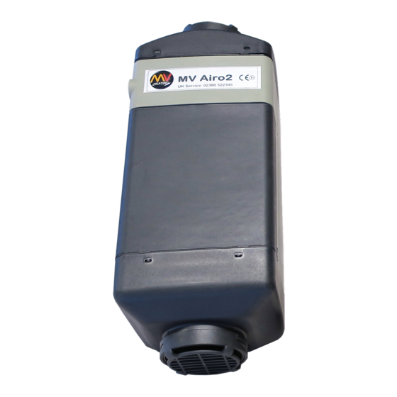
Page 5: Heater Cases Diagram
+44 (0)23 8052 2345 Heater Cases Diagram Figure 1 1. Inlet Cap 2. Outlet Cap 3. E.C.U. Cover 4. Top Cover 5. Bottom Cover 6. Grill MV Heating UK Ltd... -
Page 6: Internal Structure Diagram
Internal Structure Diagram Figure 2 1. Heat Exchanger 2. 4-Hole Gasket 3. Combustion Tube 4. Burner Assembly 5. 5-Hole Gasket 6. Air Motor 7. Insulation Bushes 8. E.C.U. 9. Air Fan 10. Glow Pin 11. Overheat Sensor MV Heating UK Ltd... -
Page 7: Ecu Connections Diagram
+44 (0)23 8052 2345 ECU Connections Diagram Figure 3 1. Fan Motor 2. Glow Pin 3. Overheat Sensor 4. Fuel Pump 5. Unused 6. Main Wiring Harness MV Heating UK Ltd... -
Page 8: Removing And Refitting Of Parts
All disassembled parts should be Inspected for damage (cracks, distortion, wear, etc.) and replaced as required. You should also regularly inspect all electrical connectors and wiring for corrosion, loose contacts, or wrong crimping, etc. and repair as required. MV Heating UK Ltd... -
Page 9: Part 1: The Case Assembly
3) Replace top case, ensuring that the tabs are locate inside the bottom case correctly. 4) Refit the outlet cap, ensuring that it is orientated correctly. 5) Refit the inlet cap, ensuring that it is orientated correctly. MV Heating UK Ltd... -
Page 10: Part 2: The Overheat Sensor
1) Replace the overheat sensor on the heat exchanger. 2) Feed the wires back under the E.C.U. hook to secure them in place. 3) Plug the overheat sensor back into the E.C.U. paying attention to its correct orientation. MV Heating UK Ltd... -
Page 11: Part 3: The E.c.u
3) Push the air fan back onto the shaft, look for the flat edge on the air fan, and the flat edge of the air motor spigot to connect the two. 4) Check the fan spins freely and reconnect the overheat sensor (Part 2), and the cases (Part 1). MV Heating UK Ltd... -
Page 12: Part 4: The Air Motor
3) Place the earth cable over the top right hex bolt, and fit the remaining 4 x hex bolts around the base of the air motor and tighten to 4.0 ± 0.4 Nm. 4) Refit E.C.U. (Part 3) and cases (Part 1). MV Heating UK Ltd... -
Page 13: Part 5: Burner, Glow Pin, And Combustion Chamber
5) Separate the two using a small flat-bladed screwdriver and remove both parts from the heat exchanger (2:1). 6) Remove the 4-hole gasket (2:2) from inside the heat exchanger and discard. MV Heating UK Ltd... -
Page 14: Part 5 Cont'd: Burner, Glow Pin, And Combustion Chamber
1) Feed the glow pin back through the appropriate slot on the burner and reinsert it fully into position. 2) Tighten the small Phillips head screw onto the glow pin to 0.8 ± 0.08 Nm to hold it securely in place. MV Heating UK Ltd... -
Page 15: Part 5 Cont'd: Burner, Glow Pin, And Combustion Chamber
5) Push the fuel inlet grommet back into position ensuring it is flush with the heat exchanger. 6) Refit the air motor (Part 4), the E.C.U. (Part 3), the overheat sensor (Part 2), and the cases (Part 1). MV Heating UK Ltd... -
Page 16: Part Numbers
10) Glow Pin (12V/24V): A2C-014/A2C-014 11) Overheat Sensor: A25Z-016 12) Inlet Cap: A2Z-027 13) Outlet Cap: A2Z-028 14) E.C.U. Cover: A2Z-024 15) Top Cover: A2Z-025 16) Bottom Cover: A2Z-026 17) Grill: A2Z-029 18) Fuel Pump (12V/24V) AHC-023/AHA-023 MV Heating UK Ltd... -
Page 17: Notes
+44 (0)23 8052 2345 Notes ……………………………………………………………………………………………………………………….. ……………………………………………………………………………………………………………………….. ……………………………………………………………………………………………………………………….. ……………………………………………………………………………………………………………………….. ……………………………………………………………………………………………………………………….. ……………………………………………………………………………………………………………………….. ……………………………………………………………………………………………………………………….. ……………………………………………………………………………………………………………………….. ……………………………………………………………………………………………………………………….. MV Heating UK Ltd... - Page 18 +44 (0)23 8052 2345 MV Heating UK Ltd...
Need help?
Do you have a question about the MV Airo 2 and is the answer not in the manual?
Questions and answers