Table of Contents
Advertisement
Quick Links
This Surge Protective Device (SPD) is a high performance device, designed to provide protection
DITEK Corporation
for sensitive electronic loads connected to communication loop circuits that have been isolated
ONE DITEK CENTER
1720 Starkey Road
Largo, FL 33771
from the public switched telephone network or where the SPD is directly connected to the
electronic device. Maximum protection will only be achieved if the SPD is properly installed.
Please read and follow the installation instructions carefully.
NOTICE: This SPD should be installed and grounded, by a licensed contractor, per the applicable
requirements of the NEC and the following instructions. These devices are only to be employed on
communication loop circuits which have been isolated from the Public Switched Telephone Network.
APPLICATION
DTK-MB10 base can be installed inside a 4"x4" electrical boxes and other locations where there is a space
constraint. This base is available as a 1 up array (standard) or 2 through 5 up array for multiple pair
terminations at one point of use. Specify DTK-2MB, 3MB, 4MB or 5MB for 2 through 5 up arrays.
DTK-2MHLPxxFWB surge module is for hardwired series installations for voltages ranging from 5-75 Volts
on circuits that operate at less than 1 Amp.
DTK-2MHLPxxBWB surge module is for hardwired series installations for voltages ranging from 5-75 Volts
on circuits that operate at less than 5 Amps.
DTK-2MHTP surge module is for hardwired series installations for dialer circuits and POTS lines for
communication circuits.
INSTRUCTIONS:
Caution: Measure all voltages to insure applied voltage does not exceed the voltage rating of the unit.
Improper installation voids the warranty.
MB BASE INSTALLATION
1. Turn off the power at the circuit to be protected before beginning installation.
2. Securely mount the snap track between the field wiring and your equipment to be protected. Use the two #8 screws
provided to fasten the snap track.
3. Connect ground to the ground terminal using a minimum of 14 AWG wire, make this conductor as short as possible.
Ground Resistance Rule: Max ground resistance is 25 Ohms, 5 Ohms or less is optimum.
This cannot be an assumed value and must be measured to assure proper grounding.
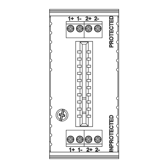
4. Connect the supply/field wiring to the UNPROTECTED side of the MB base. Connect the 1st pair to
position 1+ and 1- , than the 2nd pair to position 2+ and 2-.
5. Connect the equipment wiring to the PROTECTED side of the MB base. Connect the 1st pair to
position 1+ and 1- , than the 2nd pair to position 2+ and 2-.
6. Make sure the UNPROTECTED supply/field wiring and PROTECTED equipment wiring conductors do not occupy
the same space or conduits.
7. Make sure the wire distance from the base to protected equipment is about 3' of conductor length. This can be a
coiled service loop if necessary.
MODULE INSTALLATION
Insert the module into the base making sure the polarizing keys in the block are aligned with the notches cut into
the edge card printed circuit board.
8. After all connections have been made and no hazards exist, restore power.
SUPPLY WIRING
or FIELD WIRING
Drawn By: RMitchell 3-3-11
Revised By: RMitchell 6-14-16
DTK-2MHLPxxFWB Series, DTK-2MHLPxxBWB Series,
DTK-2MHTPWB, MB10, 2MB-5MB, and DTK-2MHLP Module
Pair 1
Pair 2
DITEK Technical Support Available 24/7
1-888-472-6100 www.ditekcorp.com
GROUNDING
#14AWG MIN.
GND
DTK-2MHLP BASE
ALLOW FOR 3' OF CONDUCTOR LENGTH
BETWEEN BASE AND PROTECTED EQUIPMENT
EQUIPMENT WIRING
3' SERVICE LOOP
Pair 1
Pair 2
Doc # INT-100132-001
Part No. 191556 Rev. 4
E
Q
U
I
P
M
E
N
T
Advertisement
Table of Contents

Subscribe to Our Youtube Channel
Related Manuals for Ditek DTK-2MHLP FWB Series

Summary of Contents for Ditek DTK-2MHLP FWB Series
- Page 1 Pair 2 Pair 2 DTK-2MHLP BASE ALLOW FOR 3’ OF CONDUCTOR LENGTH BETWEEN BASE AND PROTECTED EQUIPMENT DITEK Technical Support Available 24/7 Drawn By: RMitchell 3-3-11 Doc # INT-100132-001 1-888-472-6100 www.ditekcorp.com Revised By: RMitchell 6-14-16 Part No. 191556 Rev. 4...
- Page 2 Largo, FL 33771 1.15 1.03 Snap Track 3.25 1.50 DTK-MB10 DTK-2MHLPxxFWB DTK-2MHLPxxBWB DTK-2MHTPWB DTK-2MB DTK-4MB DTK-5MB DTK-3MB DITEK Technical Support Available 24/7 Drawn By: RMitchell 3-3-11 Doc # INT-100132-001 1-888-472-6100 www.ditekcorp.com Part No. 191556 Rev. 4 Revised By: RMitchell 6-14-16...
Need help?
Do you have a question about the DTK-2MHLP FWB Series and is the answer not in the manual?
Questions and answers