
Summary of Contents for Meridian Innovation MI0801
- Page 1 MI0801 Camera Module Evaluation Kit User Manual Version 0.D M e r i d i a n I n n o v a t i o n Page 1 of 9 www.meridianinno.com...
-
Page 2: Table Of Contents
Contents Overview ............................ 3 1.1. MI0801 Camera Module Evaluation Kit (EVK) ................ 3 1.2. EVK Internal Connections ...................... 3 1.3. MI0801 Camera Module - Bobcat ..................... 3 1.4. MI48A0 Thermal Image Processor (TIP) ................... 4 1.5. MI48A0 Thermal Image Processor Board ................. 4 1.6. External Interface Processor Board .................. 5 1.7. EVK Graphical User Interface (GUI) Software ................ 5 GUI Software ............................ 6 2.1. Minimum System Requirements .................... 6 2.2. Obtaining and Launching GUI .................... 6 2.3. Connecting via USB ........................ 6 2.4. -
Page 3: Overview
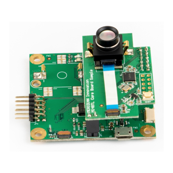
1. Overview This user manual is aimed to give users a fast introduction to the use of the MI0801 Camera Module Evaluation Kit (EVK) and its accompanying software. 1.1. MI0801 Camera Module Evaluation Kit (EVK) The EVK contains two circuit boards, the MI48A0 Thermal Image Processor and the External Interface Processor Board. This kit contains: • MI0801 Camera Module • MI48A0 Thermal Image Processor (TIP) Board • External Interface Processor Board • Graphical User Interface (GUI) software Together, these components combine to form a thermal camera system capable of capturing 80-by-62 thermal images. This kit is designed to be connected via USB to a host... -
Page 4: Mi48A0 Thermal Image Processor (Tip)
The MI48A0 TIP is a Meridian Innovation product made specifically to interface with the MI0801 Camera Module as a companion chip. It is a 5mm by 5mm QFN32 chip with a bottom thermal pad and is expected to be electronically connected to the corresponding signal pins of the MI0801 Camera Module. This companion chip performs all the low-level computations and signal timing required to process the raw data from the MI0801 Camera Module, thus removing this burden from any external processors. The MI48A0 TIP also provides the external interface which is made up of common electrical buses and interfaces. The serial peripheral interface (SPI) bus is provided to transfer thermal image data with the MI48A0 TIP as a SPI slave device. The Inter-Integrated Circuit (I... -
Page 5: External Interface Processor Board
1.6. External Interface Processor Board The External Interface Processor Board is an example of an external system that interfaces with the MI48A0 TIP using the TIP External Interface. The external processor is the Nuvoton M484SIDAE. This External Processor Board is shipped pre-loaded with Meridian Innovation’s firmware to demonstrate the TIP External Interface communication protocol. The External Processor Board also features a USB Micro B connector plug, and should be connected to a host PC via a USB 2.0 High-speed (HS) port for power and communication. -
Page 6: Gui Software
2. GUI Software The following sections describe how to obtain, run and operate the GUI on a Windows-based computer with a USB 2.0 High-Speed connector socket. 2.1. Minimum System Requirements The GUI currently only supports computers running Windows 7, 8/8.1, 10. It also requires at least one USB 2.0 port supporting USB High-speed mode. 2.2. Obtaining and Launching GUI Please contact us to obtain the GUI software in a ZIP file. After obtaining and downloading the ZIP file, extract (a.k.a. unzip) the contents into a convenient directory. Inside the directory with the extracted files, run the file in .exe. Note that most GUI controls are disabled upon launch. 2.3. -
Page 7: Capturing Image
2.4. Capturing Image Press the “Get Single” button under “SenXor Controls”. The EVK will capture a thermal image, which will be transmitted to and displayed on the GUI. Note that LED1 on the EVK may blink multiple times. LED1 indicates that frame(s) are being captured and processed by the EVK. Press the “Get Continuous” button under “SenXor Controls”. The EVK will begin to continuously capture thermal images, and the GUI display will be continuous updated. Note that LED1 will blink continuously, and the “FPS” counter under “SenXor Controls” on the GUI will also continuously update to report the framerate of the EVK. “FPS” here stands for Frames Per Second. The FPS is mainly affecting the internal frame averaging. -
Page 8: Color Palette And Scaling
2.6. Color Palette and Scaling The GUI performs its own post-processing functions (i.e. processing down on the host PC) before displaying the thermal data received over USB. One such function is to apply color to pixel values so that temperature differences are more visually significant. Under “Color Palette and Scaling”, there are a drop-down control to select different pre- set color palette mapping to the temperature value. The “Auto?” checkbox selects whether the color palette is scaled automatically to cover the minimum and maximum temperatures of the currently displayed image. While this is checked, “Scale Min” and “Scale Max” controls display the minimum and maximum temperature values. While this is unchecked, the “Scale Min” and “Scale Max” controls allow the user to manually adjust the minimum and maximum temperatures of the color scale. -
Page 9: Pixel Filter
2.7. Pixel Filter Another GUI post-processing function is the pixel filter. In traditional image processing terms, this function is equivalent to apply a 2D convolution to the thermal image with a NxN mask, where N is set to be 0, 3 or 5 corresponding to Sharp, Smooth and Blurred currently. The GUI controls for these parameters are available under the “Pixel Filter” sections of the GUI. A pixel filter performs spatial filtering of the image, in order to reduce noise and effective in removing “salt and pepper noise” in temperature images. Note that the effective image size is reduced when a pixel filter is applied. For a mask of size 3, the top, left, right and bottom image border pixels are disregarded and hence the effective image size is reduced by 2 rows and 2 columns. For a mask of size 5, the effective image size is reduced by 4 rows and 4 columns. 2.8. Temperature Unit By default, all temperatures values displayed on the GUI is in degrees Celsius. This can be modified to degree Fahrenheit or Kelvin. 2.9. Multiple EVK connection If there are more than one EVK connecting to the device, the GUI can expand to multiple widgets for different EVK. Under “Action” -> ”Add New Viewer” tag and new widget can be added on the left or right to the main window. Widget Ctrl controls the corresponding widget swap with left, close or swap with right widget.
Need help?
Do you have a question about the MI0801 and is the answer not in the manual?
Questions and answers