Table of Contents
Advertisement
Advertisement
Table of Contents

Summary of Contents for Rae FTB 1000
- Page 1 RAE PowerPak User’s Guide \\\\\ Rev. A July 2009 P/N F03-4001-000...
- Page 2 © Copyright 2009 RAE Systems, Inc. Ordering Replacement Parts: If you need replacement parts, a list is available online: http://www.raesystems.com...
-
Page 3: Table Of Contents
Charging The RAE PowerPak ........24 Troubleshooting & Repair ..........27 14.1 Encapsulated Internal Battery Replacement .... 27 14.2 Batteries And Proper Battery Disposal ....31 Specifications ..............32 Appendix A: Controlled Part Of RAE PowerPak (FTB1000) Manual ..............33... -
Page 4: Safety Instructions
Substitution of components may impair suitability for intrinsic safety. Replace encapsulated internal batteries only in non- hazardous locations. Warning: Charging of the FTB 1000 by means of mains charger can only be done in safe area and only with RAE Systems Charger P/N F03- 3012-000. Warning: The internal encapsulated battery units can only be exchanged with the original RAE Systems battery. -
Page 5: Rae Powerpak Marking
RAE PowerPak User’s Guide RAE PowerPak Marking The RAE PowerPak is certified according to the IECEx scheme, ATEX and CSA for US and Canada as protected by intrinsic safety. The product is marked with the following information: RAE PowerPak Type FTB1000. -
Page 6: Operation Area And Conditions
Operation Area and Conditions Hazardous Areas classified by Zones RAE PowerPak is intended to be used in mines susceptible to firedamp or hazardous areas classified for zone 0, zone 1 or zone 2, within the temperature range of -40º C to +55º C, where gases of explosion groups IIA, IIB or IIC and T4 may be present. -
Page 7: Use In Hazardous Areas
RAE PowerPak User’s Guide Use In Hazardous Areas Equipment which is intended for use in explosive atmospheres and which has been assessed and certified according to international regulations may be used only under specified conditions. The components may not be modified in any way. -
Page 8: Standard Kit
RAE PowerPak User’s Guide Standard Kit RAE PowerPak (FTB1000), as specified with two or four encapsulated internal batteries. Cable for connecting MeshGuard to RAE PowerPak: D01-3003-000 General Information The RAE PowerPak (FTB-1000) is an intrinsically safe rechargeable battery power source for use with a MeshGuard EC or MeshGuard LEL monitor or MeshGuard Router or any other equipment with matching entity parameters. -
Page 9: Key Features
RAE PowerPak User’s Guide Key Features Up to 4 months continuous operation before recharging, when it contains four encapsulated internal batteries and is used with a MeshGuard (4 months), MeshGuard LEL (25 days), or MeshGuard Router (1.5 months) Rugged stainless-steel enclosure ... -
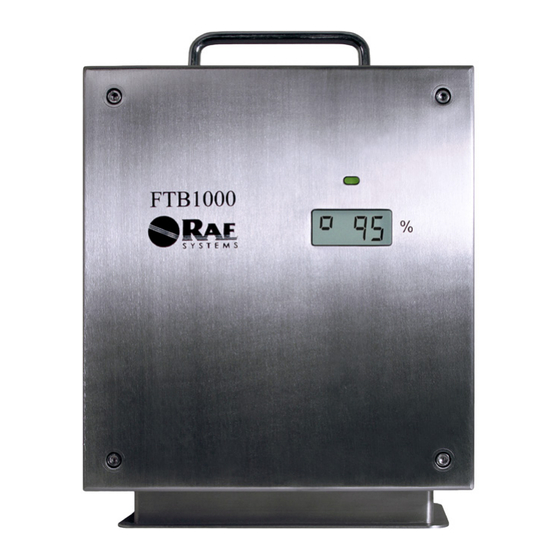
Page 10: Physical Description
RAE PowerPak User’s Guide Physical Description Front View Bottom View Carrying handle Stainless steel enclosure Status LED Status LCD Protective bezel for connections Power output port to MeshGuard Power output dust cap Power input from charger Power input dust cap... -
Page 11: Lcd & Led
RAE PowerPak User’s Guide LCD & LED The RAE PowerPak has a single LED and an LCD that indicates charge, and in the case of errors any messages. 3-color LED LED Status Indicator The LED glows red, orange, or green, depending on different status alerts it is conveying. -
Page 12: Lcd Status Information & Error Messages
RAE PowerPak User’s Guide LCD Status Information & Error Messages Error codes may appear in the LCD, indicating battery or fuse conditions, as well as temperatures outside the normal operating range. Error Code Message Battery 1 voltage too low Er01... - Page 13 Replace it with the correct type. Er14: The wrong type of charger is being used. The correct RAE Systems charger (part number F03-3014-000) identifies itself to the RAE PowerPak. Er15: An internal fuse has been blown. Fuses on the main circuit board cannot be replaced.
-
Page 14: Installation
RAE PowerPak User’s Guide Installation The RAE PowerPak is designed to be located close to a detector such as a MeshGuard, MeshGuard LEL or MeshGuard Router. To accommodate this, and to ensure security, both are mounted on a steel plate, which can be attached to a wall or other flat vertical surface. - Page 15 RAE PowerPak User’s Guide Secure the plate to a wall or other solid, flat surface by using M8- size screws with flat washers and locking washers, following this diagram. At a minimum, use four screws at the corners. (The MeshGuard has been removed from the drawing for simplicity.)
- Page 16 RAE PowerPak User’s Guide Next mount the RAE PowerPak onto the steel plate. Note: Make sure the RAE PowerPak has been fully charged before installation. Align the RAE Slide the RAE PowerPak PowerPak with the rails down until it stops...
-
Page 17: Operation Instructions
RAE PowerPak User’s Guide Operation Instructions The FTB 1000 Power Pack is only to be used with RAE Systems products whose entity parameters match the entity parameters of the RAE PowerPak. Input Output Fig. 1 Connections Fig. 2 RAE PowerPak connected to the MeshGuard. -
Page 18: Connection
Note: The following steps must be performed outside the hazardous area or with a “hot zone” permit. Now connect the cable between the RAE PowerPak and the MeshGuard. With the MeshGuard or MeshGuard LEL securely in its housing, you can remove the cover over the battery compartment so that you can replace the internal battery in the MeshGuard. - Page 19 Do not overtighten. On the bottom of the RAE PowerPak are two dust caps that are screwed onto the connectors: Unscrew the one on the left by turning it counterclockwise. When...
- Page 20 RAE PowerPak User’s Guide Screw the end of the connecting cable to the port on the bottom of the RAE PowerPak. Do not use tools or overtighten.
-
Page 21: Changing The Rae Powerpak
RAE PowerPak User’s Guide Changing The RAE PowerPak 1. Unscrew the battery connector from the RAE PowerPak. 2. Loosen the safety screw holding the battery latch. - Page 22 RAE PowerPak User’s Guide 3. Raise the latch. 4. Lift up the battery and slide it off the steel plate.
- Page 23 RAE PowerPak User’s Guide 5. Mount a fully charged RAE PowerPak on the mounting bracket. 6. Flip the latch down. 7. Tighten the safety screw.
-
Page 24: Charging The Rae Powerpak
PowerPak shows a low-power reading (10% or less), you should charge it in a safe location. 1. If the RAE PowerPak is currently in service and is attached to a MeshGuard, follow the instructions for removing it, on page 2. Remove the cap over the charging port on the bottom of the... - Page 25 RAE PowerPak User’s Guide 3. In a safe location, connect the charging cable between the RAE PowerPak and the Charger and connect the AC mains cord from the Charger to an AC power plug. 4. The LED above the display should glow red and the display should say “CHRG.”...
- Page 26 8. Screw the cap back on over the charging port on the bottom of the RAE PowerPak. 9. Place the RAE PowerPak on the steel mounting plate (detailed instructions are shown on page 14). 10. Follow the insructions on page 17 to reconnect the RAE...
-
Page 27: Troubleshooting & Repair
RAE PowerPak User’s Guide Troubleshooting & Repair The RAE PowerPak is designed to be trouble-free and require no maintenance. However, if you see the status LED glow orange and an error message in the display, refer to the error message table on page 12 and take the suggested action. - Page 28 RAE PowerPak User’s Guide 1. Unscrew the four screws on the front of the enclosure. 2. Disconnect the battery’s power jumper from the main printed circuit board.
- Page 29 RAE PowerPak User’s Guide 3. Remove the screws at both ends of the battery. These attach the bracket that holds the battery in place. 4. Lift out the bracket and the battery.
- Page 30 RAE PowerPak User’s Guide 5. Insert a new battery and the bracket into the enclosure. 6. Replace the two screws and tighten them with a screwdriver. Before replacing the front cover, check the display. If it is not working, then the ribbon cable between the display and the main circuit board might have become disconnected.
-
Page 31: 14.2 Batteries And Proper Battery Disposal
RAE PowerPak User’s Guide The display should indicate the correct number of batteries. If not, check that the connector between the battery and the circuit board is firmly connected. 7. Once everything checks out, replace the front cover and tighten the screws. -
Page 32: Specifications
RAE PowerPak User’s Guide Specifications Display Customized LCD and red/orange/green LED Dimensions 36.2 cm x 26 cm x 14.6 cm (14.25″ H x 10.25″ W x 5.75″ D) Weight 15 kg (33 lbs) with four internal batteries Package IP-65 Output 3.3V±0.1V... -
Page 33: Appendix A: Controlled Part Of Rae Powerpak (Ftb1000) Manual
Substitution of components may impair suitability for intrinsic safety. Replace encapsulated internal batteries only in non- hazardous locations. Warning: Charging of the FTB 1000 by means of mains charger can only be done in safe area and only with RAE Systems Charger P/N F03- 3012-000. Warning: The internal encapsulated battery units can only be exchanged with the original RAE Systems battery. - Page 34 RAE PowerPak User’s Guide RAE PowerPak Marking The RAE PowerPak is certified according to the IECEx scheme, ATEX and CSA for US and Canada as protected by intrinsic safety. The product is marked with the following information: RAE PowerPak Type FTB1000.
- Page 35 Operation Area and Conditions Hazardous Areas classified by Zones RAE PowerPak is intended to be used in mines susceptible to firedamp or hazardous areas classified for zone 0, zone 1 or zone 2, within the temperature range of -40º C to +55º C, where gases of explosion groups IIA, IIB or IIC and T4 may be present.
- Page 36 RAE PowerPak User’s Guide Use In Hazardous Areas Equipment which is intended for use in explosive atmospheres and which has been assessed and certified according to international regulations may be used only under specified conditions. The components may not be modified in any way.
- Page 37 RAE Systems by Honeywell World Headquarters 3775 N. First St. San Jose, CA 95134-1708 USA Phone: 408.952.8200 Toll-Free: 888.723.4800 Fax: 408.952.8480 Rev. A July 2009 P/N F03-4001-000...
Need help?
Do you have a question about the FTB 1000 and is the answer not in the manual?
Questions and answers