
Related Manuals for TEUPEN LEO 15 GT


Summary of Contents for TEUPEN LEO 15 GT
- Page 1 Serial number: _______________ Translation of the original oper- ating instructions Aerial access platform...
- Page 2 TEUPEN Maschinenbau GmbH Marie-Curie-Straße 13 D-48599 Gronau Telephone: +49 (0) 2562 8161-0 Fax: +49 (0) 2562 8161-888 email: info@teupen.com Internet: www.teupen.com Service: Telephone: +49 (0) 2562 8161-313 email: service@teupen.com © TEUPEN Maschinenbau GmbH 2013 Aerial access platform Leo15GT 2012 13.02.2013...
-
Page 3: Table Of Contents
Table of contents Table of contents General..............7 1.1 Information about these instructions..... 7 1.2 Explanation of symbols......... 7 1.3 Limitation of liability........9 1.4 Copyright............9 1.5 Warranty provisions........10 1.6 Conditions warranty performance card..10 1.7 Customer Service........11 Safety.............. - Page 4 Table of contents 3.6.1 Combustion engines........ 41 3.6.2 Electric motor........... 42 3.7 Emissions............ 42 3.8 Operating conditions........42 3.9 Hydraulic system......... 42 3.10 Lubricants..........43 3.11 Type plate..........44 Structure and function........45 4.1 Overview............. 45 4.2 Brief description.......... 46 4.3 Assembly description........
- Page 5 Table of contents 6.5 Putting the machine in work position... 72 6.5.1 Manual bracing......... 73 6.5.2 Automatic bracing........75 6.6 Operating the machine........ 77 6.7 Putting the machine in transport position..79 6.8 Height and width adjustment crawler chassis (optional)........84 6.9 Changing the working basket......
- Page 6 Table of contents 8.6.2 Working basket fuse and FI circuit breaker........... 136 Disposal............137 9.1 Safety instructions for disposal....137 9.2 Disposal............ 137 10 Index..............139 Appendix............141 Combustion engine........145 A.1 Gasoline engine Robin-Subaru EX 21..147 A.2 Diesel engine Hatz 1B30 (optional)..... Circuit diagram..........
-
Page 7: General
General General 1.1 Information about these instructions These instructions enable the safe and efficient han- dling of the machine. These instructions are a compo- nent of the machine and must be kept in the immediate vicinity of the machine so that they are accessible to the personnel at any time. - Page 8 General CAUTION! This combination of symbol and signal word indicates a possibly-dangerous situation which could cause slight injuries if it is not avoided. NOTICE! This combination of symbol and signal word indicates a possibly-dangerous situation which could cause property and environ- mental damage if it is not avoided.
-
Page 9: Limitation Of Liability
General Marking Explanation Listing without fixed sequence [Buttons] Operating elements (e.g. buttons, switches), display elements (e.g. signal lamps) ‘Display’ Screen elements (e.g. buttons, pro- gramming of function keys) 1.3 Limitation of liability All details and instructions in these instructions were compiled taking into account the applicable standards and regulations, the state of technology, as well as our many years of knowledge and experience. -
Page 10: Warranty Provisions
Teupen directly after hand- over of the machine to the customer. If the warranty... -
Page 11: Customer Service
General Fig. 1: Sample warranty card 1.7 Customer Service Our Customer Service is available for technical informa- tion. Please see page 2 for the contact data. In addition, our employees are constantly interested in new information and experiences which arise from usage and could be valuable for the improvement of our products. - Page 12 General Aerial access platform Leo15GT 2012 13.02.2013...
-
Page 13: Safety
Safety Safety This section provides an overview of all safety aspects that are essential to the best possible protection of the personnel and the safe and trouble-free operation of the machine. Additional safety instructions for specific work tasks are contained in the sections regarding the indi- vidual life stages of the machine. - Page 14 Safety Work in high places WARNING! Risk of falling! During work in high places, there is a risk of falling. This can cause severe injuries or even death. – Always wear a safety harness (acc. to EN 361) when in the working basket and do not swing or move jerk.
-
Page 15: Danger Due To Electric Current
Safety 2.1.2 Danger due to electric current Electric current DANGER! Danger to life due to electric current! Upon contact with voltage-conducting parts, there is an immediate danger to life due to electric shock. Damage to the insulation or individual components can present a danger to life. - Page 16 Safety Batteries WARNING! Danger of injury due to incorrect handling of batteries! In case of batteries are improperly handled, there is the danger that the batteries can explode or that liquids that are hazardous to health can egress from the batteries. The liquid egressing can cause severe burns upon skin contact, severe poisoning upon swallowing and blindness in case it comes in...
-
Page 17: Danger Due To Mechanical Elements
Safety 2.1.3 Danger due to mechanical elements Falling materials WARNING! Danger of injury due to falling materials! During operation, material can fall down uncontrolled and cause severe injuries. – Make others aware of the danger zone and block off the area. –... -
Page 18: Danger Due To Hydraulic Energies
Safety Crawler chassis WARNING! Danger of injury due to driving over body parts! With the crawler chassis, there is a danger of pinching off body parts and thus causing severe to fatal injuries. – During operation, do not reach into run- ning chains or chain wheels. -
Page 19: Dangers Due To High Temperatures
Safety 2.1.5 Dangers due to high temperatures Hot surfaces WARNING! Danger of injury due to hot surfaces! Surfaces of engine components can get heated up considerably during operation. Skin contact with hot surfaces causes severe burns to the skin. – Avoid contact with engine components such as exhaust components, silencers, coolers, radiators, pipes and engine blocks. -
Page 20: Danger Due To Traffic And Vehicles
Safety Engine oil WARNING! Danger of injury through engine oil! Engine oil contains poisonous substances which can cause inflammations and / or are carcinogenic. – Avoid all skin contact with engine oil. – In case of accidental skin contact, wash the hands or affected area immediately with soap. -
Page 21: Proper Use
Safety 2.2 Proper use The machine is designed and constructed exclusively for the proper use described here. The machine is to be used exclusively to convey people and tools up to the maximum allowable working basket load to perform work in high places. Proper use also includes adherence to all details in these instructions. - Page 22 Safety In addition to the safety instructions in these instruc- tions, the valid safety, accident prevention and environ- mental protection regulations applicable to the machine's area of application must be adhered to. Here, the following points apply in particular: The owner must inform himself about the applicable occupational safety provisions and also determine in a risk assessment the risks which arise due to the specific working conditions in the place where the...
-
Page 23: Personnel Requirements
Safety 2.4 Personnel requirements 2.4.1 Qualifications WARNING! Danger of injury in case of insufficient qualification of the personnel! If unqualified personnel undertakes work on the machine or is in the machine's danger zone, dangers arise which can cause severe injuries and significant property damage. –... - Page 24 Safety Qualified Electrician Based on his technical training, knowledge, experience and knowledge of the applicable standards and regula- tions, the Qualified Electrician is able to perform work on electrical systems and recognise and avoid potential hazards himself. The Qualified Electrician is specially trained for the area of responsibility he is involved with and knows the rele- vant standards and regulations.
-
Page 25: Unauthorised Persons
Safety 2.4.2 Unauthorised persons WARNING! Risk to life for unauthorised persons due to hazards in the danger and working zone! Unauthorised persons who do not meet the requirements described here will not be familiar with the dangers in the working zone. Therefore, unauthorised persons face the risk of serious injury or death. - Page 26 Safety Description of the personal pro- The personal protective equipment is explained below: tective equipment Protective clothing Protective clothing are tight fitting working clothes with low tear resistance, with tight sleeves and without any parts sticking out. These clothes primarily protect against getting caught by moving machine parts.
-
Page 27: Safety Equipment
Safety 2.6 Safety equipment WARNING! Danger to life from nonfunctional safety devices! If safety devices are not functioning or are disabled, there is a danger of grave injury or death. – Check that all safety devices are fully functional and correctly installed before starting work. - Page 28 Safety View from the left side Fig. 2: Position of the safety equipment Limit switch outriggers Valves for emergency/service operation Limit switch, transport lock lower boom chains/bracing function Limit switch, locking bolts Aerial access platform Leo15GT 2012 13.02.2013...
-
Page 29: Description Of The Installed Safety Equipment
Safety View from the right side Fig. 3: Position of the safety equipment Emergency Stop button on the control Tilt sensor (covered) panel/cable remote control Valves for emergency/service operation Limit switch, transport lock upper boom platform function Circular level 2.6.2 Description of the installed safety equipment Emergency Stop button By pressing the Emergency Stop button, the machine is... - Page 30 Safety WARNING! Danger to life due to uncontrolled switching on again! Uncontrolled switching on again of the machine can cause severe injuries or even death. – Ensure before switching on again that the cause of the emergency stop has been eliminated and all safety equipment is mounted and functioning properly.
-
Page 31: Symbols On The Machine
Safety Fig. 7: Circular level Valves for emergency and service operation During power failure or for maintenance purposes it is possible to operate the aerial access platform in Emer- gency or in service operation. Using various valves (Fig. 8), it is possible to address and move the corre- sponding components without power supply. - Page 32 Safety Sample item number Fig. 9: Sample item number Each sticker has an item number (example: Fig. 9/1). This item number can be attached to various location on the sticker. The item numbers always consist of the numeric sequence 3912 followed by a 4-digit number. In the example Fig.
-
Page 40: Behaviour In Case Of Fire Or Accidents
Safety 2.8 Behaviour in case of fire or accidents Preventive measures Be prepared for fire and accidents at all times! Keep first-aid equipment (first-aid kit, blankets, etc.) and fire extinguishing devices operational and readily available. Make your personnel familiar with accident reporting equipment as well as first-aid and rescue equipment. -
Page 41: Environmental Protection
Safety 2.9 Environmental protection NOTICE! Danger to the environment due to incor- rect handling of materials which can harm the environment! In case of incorrect handling of materials which can harm the environment, especially improper disposal, there can be significant damage to the environment. - Page 42 Safety Cooling water - frost protection Cooling water and frost guards contain toxic sub- stances. They must not be allowed to escape into the environment. Disposal must be carried out by a spe- cialist disposal company. Rechargeable batteries or bat- Rechargeable batteries and batteries contain toxic teries heavy metals.
-
Page 43: Technical Data
Technical data Technical data 3.1 Dimension sheet 3.1.1 Main dimensions Fig. 12: Main dimensions 3.1.2 Work diagram Fig. 13: Work diagram 13.02.2013 Aerial access platform Leo15GT 2012... -
Page 44: Machine
Technical data 3.2 Machine Data Value Unit Overall length 5.25 m Overall length without working 4.52 m basket Overall width 0.78 m Overall height 1.99 m Gross weight* 1750 kg Carrying capacity while driving 4.65 kN/m Carrying capacity in working 1.98 kN/m position * Possible weight deviation due to:... -
Page 45: Bracing
Technical data Data Value Unit Climbing ability 17 (30) ° (%) Slope angle 17 (30) ° (%) Travel speed 1.0 km/h Max. chassis clearance 15 cm *Option 3.5 Bracing Data Value Unit Max. bracing width 3.13 m Min. bracing width 2.95 m Bracing pad Ø... -
Page 46: Electric Motor
Technical data 3.6.2 Electric motor EMG-EBS 90 LX4 Data Value Unit Voltage 230 V Frequency 50 Hz Current consumption 12.9 A Output 2.2 kW Cable lengths Data Value Unit Maximum cable length with 40 m cable diameter 3 x 2.5 mm Maximum cable length with 80 m cable diameter 3 x 4.0 mm... -
Page 47: Lubricants
50 l system Fill quantity of the hydraulic approx. 25 l tank 3.10 Lubricants Lubricant Type TEUPEN item number Fill level Unit Gearbox oil Gearbox oil 3917/0122 * max. 1 l Hydraulic oil Plantohyd 32-S 3917/0066 * 50 l... -
Page 48: Type Plate
Technical data 3.11 Type plate Fig. 14: Sample type plate The type plate is located on the lift arm holder below the valves for emergency operation. It includes the fol- lowing data: Manufacturer Type Serial number Year of manufacture Net weight Load capacity Permitted number of people Payload... -
Page 49: Structure And Function
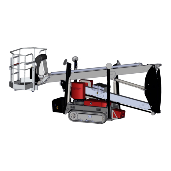
Structure and function Structure and function 4.1 Overview Overview from the left side Fig. 15: Overview Outrigger 2 Control box cover Base plates Left crawler chassis Outrigger 1 Height/width adjustment of the crawler Control head with control panel/cable chassis (optional) remote control and 230 V outlet Valve cover for bracing/chain function Working basket... -
Page 50: Brief Description
Structure and function Overview from the right side Fig. 16: Overview Outrigger 4 Valve cover for bracing/chain function Upper boom with telescopic arm Right crawler chassis Outrigger 3 Control box cover Linkage Lift arm holder Lower boom Document box (operating instructions, Height/width adjustment of the crawler circuit diagram, hydraulic plan) chassis (optional) -
Page 51: Assembly Description
Structure and function The operation is done either via the power network (construction side feed) using an extension cable Ä ‘Cable lengths’ on page 42) or by the combustion engine (Fig. 16/9). 4.3 Assembly description 4.3.1 Platform Fig. 17: Platform (similar to illustration) The work platform consists essentially of the lift arm holder (Fig. -
Page 52: Outriggers
Structure and function 4.3.2 Outriggers Fig. 18: Machine in work position With the help of the outriggers (Fig. 18/1 to 4), the chassis is lifted and the aerial access platform is thus put into the working position. The outriggers are num- bered consecutively according to the position numbers. -
Page 53: Crawler Chassis
Structure and function 4.3.4 Crawler chassis Ä Chapter 6.7 ‘Putting the In the transport position ( machine in transport position’ on page 79), the aerial access platform can be moved with the help of the chain drive. Only a grease gun is required for the chain tensioning. -
Page 54: Operating And Display Elements
Structure and function 4.4 Operating and display elements 4.4.1 Control panel/Cable remote control The control takes place via a control panel, which can also be used as a cable remote control. Fig. 23: Control panel/cable remote control (similar to illustration) Rocker switch function selection Right control lever Left control lever... -
Page 55: Controller For Emergency And Service Operation
Structure and function 5 - Right control lever Depending on the operating function selected and the position of the pre-selection lever, the functions marked in colour can be executed with the right control lever. 6 - Pre-selection lever Various function groups are selected with the pre-selec- tion lever. -
Page 56: Display At The Control Box
Structure and function 4.4.3 Display at the control box A display (Fig. 25/1) that shows the error codes and error names is located in the control box Ä Chapter 8.3 ‘Error code list’ on page 127). Fig. 25: Display 4.5 Power connection The connection for the electric motor is provided via a 230 V cable (Fig. -
Page 57: Accessories
Structure and function 4.7 Accessories 4.7.1 Keys The scope of supply includes various keys. They are used, among other things, for opening the control desk, control box, etc. Fig. 28: Keys 4.7.2 Safety harness (optional) A safety harness must be worn for all work in the working basket. - Page 58 Structure and function Aerial access platform Leo15GT 2012 13.02.2013...
-
Page 59: Transport And Storage
Transport and storage Transport and storage 5.1 Safety instructions for transport Improper transport WARNING! Danger to life due to improper transport! Improper transport can cause severe injuries or even death. – During transport of the aerial access plat- form, do not stay in the working basket. –... -
Page 60: Transport
Transport and storage 5.3 Transport Attachment points The following attachment points are provided: Fig. 30: Attachment points 1 Attachment points for transport with a crane 2 Attachment points for transport with a fork lift (continuous) 3 Lashing eyes for transport on a trailer (on both sides) Attachment points for transport with a crane Fig. - Page 61 Transport and storage Lashing eyes for transport on a trailer Fig. 33: Lashing eye Transport with a crane Transport pieces can be transported with a crane under the following conditions: The crane and lifts must be designed for the weight of the aerial access platform.
- Page 62 Transport and storage Attaching Protective equipment: Protective helmet Safety boots WARNING! Property damage due to improper attach- ment! The use of unsuitable attachment points can cause damage to the machine. – Only use the attachment points specified here. Put the machine in transport position Ä...
- Page 63 Transport and storage Transport Protective equipment: Protective helmet Safety boots Put the machine in transport position Ä Chapter 6.7 ‘Putting the machine in transport position’ on page 79). Switch off the machine ( Ä Chapter 6.2 ‘Switching the machine on/off’ on page 63). Insert the forks of the fork lift into the adapters pro- vided (Fig.
- Page 64 Transport and storage Loading Protective equipment: Protective helmet Safety boots WARNING! Danger of injury due to improper moving of the aerial access platform! With improper moving, the machine can tip or slide. This can cause severe injuries and sig- nificant property damage. –...
-
Page 65: Storage
Transport and storage Anchor and secure the aerial access platform to the means of transport, e.g. with safety belts in the lashing eyes (Fig. 39/1). Fig. 39: Lashing eyes The lashing eyes are marked with the Fig. 40 symbol. Begin transport. Fig. - Page 66 Transport and storage Aerial access platform Leo15GT 2012 13.02.2013...
-
Page 67: Operation
Operation Operation 6.1 Safety instructions for operation Improper operation WARNING! Danger of injury due to improper opera- tion! Improper operation can cause severe injuries and significant property damage. – Execute all operating steps according to the details and instructions in these instructions. -
Page 68: Switching The Machine On/Off Via The Mains Supply
Operation 6.2.1 Switching the machine on/off via the mains supply DANGER! Danger to life due to electric current! Upon contact with voltage-conducting parts, there is an immediate danger to life due to electric shock. Damage to the insulation or individual components can present a danger to life. -
Page 69: Switching The Machine On/Off Via The Combustion Engine
Operation Switching off Disconnect the plug (Fig. 42/1) from the extension cable or press Emergency Stop. Fig. 42: 230V connection Switching the machine on/off via the combustion 6.2.2 engine See also operating instructions for the combustion engine (see supplier documents in appendix of machine record). -
Page 70: Shutting Down In Case Of Emergency
Operation Switching on and off during operation is done using the engine switch (Fig. 43/1) at the control panel. Fig. 43: Engine switch Switching on To start the combustion engine press the motor switch (Fig. 44) upwards . Immediately let go of the motor switch once the combustion engine starts. - Page 71 Operation If necessary, start first aid measures. Inform the fire brigade and/or rescue service. Inform responsible people in the deployment loca- tion. Switch off the machine and secure against switching on again. 13.02.2013 Aerial access platform Leo15GT 2012...
-
Page 72: Moving The Machine
Operation 6.4 Moving the machine Personnel: Trained people Protective equipment: Protective clothing Safety boots Protective helmet Safety harness Aerial access platform Leo15GT 2012 13.02.2013... - Page 73 Operation WARNING! Danger of injury due to improper moving of the aerial access platform! There is a danger of severe injuries or even death due to improper moving of the aerial access platform. – Only move machine in transport position. –...
- Page 74 Operation Moving the machine can either be carried out from the working basket or with the control panel as cable remote control. Switch on the machine ( Ä Chapter 6.2 ‘Switching the machine on/off’ on page 63). Set the function selection switch (Fig. 46) in centre position to [chain function] (red).
- Page 75 Operation Table "Moving the machine" Fig. 48: Driving directions No. Operation Effect Press both control levers forwards The machine moves forwards Press left control lever forwards and Machine turns clockwise on the spot pull right control lever backwards Pull both control levers backwards The machine moves backwards Pull left control lever backwards and Machine turns anti-clockwise on the spot...
-
Page 76: Putting The Machine In Work Position
Operation 6.5 Putting the machine in work position Personnel: Trained people Protective equipment: Protective clothing Safety boots Protective helmet Safety harness WARNING! Danger of injury due to improper bracing! With improper bracing, the machine can tip or slide. This can cause severe injuries and sig- nificant property damage. -
Page 77: Manual Bracing
Operation 6.5.1 Manual bracing Ä Chapter 6.2 ‘Switching Manual bracing Switch on the machine ( the machine on/off’ on page 63). Set function selection switch (Fig. 49) to [outrigger function] (yellow). Fig. 49: Function selection switch With the pre-selection lever select the outriggers 1 and 2 (Fig. - Page 78 Operation Extend the outriggers evenly according to the table: Pre-selection Operation Symbol Effect lever posi- tion Press left control lever forwards Outrigger 1 extends Press right control lever forwards Outrigger 2 extends Press left control lever forwards Outrigger 3 extends Press right control lever forwards Outrigger 4 extends...
-
Page 79: Automatic Bracing
Operation 6.5.2 Automatic bracing Ä Chapter 6.2 ‘Switching Switch on the machine ( the machine on/off’ on page 63). Set function selection switch (Fig. 52) to [outrigger function] (yellow). Fig. 52: Function selection switch Using the pre-selection lever, select the [auto function] (Fig. - Page 80 Operation WARNING! Danger of injury due to uneven lifting! With uneven lifting, the machine can tip or slide. This can cause severe injuries and sig- nificant property damage. – In case of uneven lifting, cancel the process immediately and align the machine manually.
-
Page 81: Operating The Machine
Operation 6.6 Operating the machine Personnel: Trained people Protective equipment: Protective clothing Safety boots Protective helmet Safety harness WARNING! Danger of injury due to improper opera- tion! Improper operation can cause severe injuries and significant property damage. – While in the working basket, always wear a safety harness, do not swing or move jerkily. - Page 82 Operation Select the platform functions (Fig. 56/1 or 2) with the pre-selection lever. If the upper boom is still in the transport position, the lower boom must be lifted first so that the upper boom comes out of the transport lock. Operate the platform according to the table: Fig.
-
Page 83: Putting The Machine In Transport Position
Operation NOTICE! Property damage due to incorrectly- aligned platform! If the platform is not aligned correctly, the transport locks can be damaged when moving in. – Make sure that the red arrows (Fig. 57/1) on the rotating assembly are aligned with one another when moving into the trans- Fig. - Page 84 Operation WARNING! Danger of injury when lowering! Due to uneven lowering of the outriggers, the machine can tip or slide. This can cause severe injuries and significant property damage. – Always put the safety harness on when in the working basket. –...
- Page 85 Operation Lower upper boom completely Ä Chapter 6.6 ‘Operating the machine’ on page 77). Set function selection switch (Fig. 60) to [outrigger function] (yellow). Fig. 60: Function selection switch With the pre-selection lever select the outriggers 1 and 2 (Fig. 61/1) or 3 and 4 (Fig. 61/2). Fig.
- Page 86 Operation Retract the outriggers evenly according to the table: Pre-selection Operation Symbol Effect lever posi- tion Press left control lever forwards Outrigger 1 retracts Press right control lever forwards Outrigger 2 retracts Press left control lever forwards Outrigger 3 retracts Press right control lever forwards Outrigger 4 retracts...
- Page 87 Operation NOTICE! Property damage due to incorrectly- aligned platform! If the platform is not aligned correctly, the transport locks can be damaged when moving in. Put the platform in transport position Ä Chapter 6.6 ‘Operating the machine’ Fig. 62: Red arrows on page 77).
-
Page 88: Height And Width Adjustment Crawler Chassis (Optional)
Operation 6.8 Height and width adjustment crawler chassis (optional) Personnel: Trained people Protective equipment: Protective clothing Safety boots Protective helmet WARNING! Danger of injury due to improper height/ width adjustment! With improper height/width adjustment, the machine can tip or slide. This can cause severe injuries and significant property damage. - Page 89 Operation Insert the locking lever (Fig. 66/1) for the chassis adjustment in the locking bolts (Fig. 66/2). The locking lever for the chassis adjust- ment is located behind the control box cover. WARNING! Danger of injury due to crushing Fig. 66: Locking lever between crawler chassis and floor! When operating the chassis adjustment, there can be severe injuries due to...
- Page 90 Operation Lift the machine up using the outriggers until the crawler chassis is unloaded (Fig. 68/h = max. Ä Chapter 6.5 ‘Putting the machine in 20 mm) ( work position’ on page 72). Fig. 68: Unload the crawler chassis Insert the locking lever (Fig. 69/1) for the chassis adjustment in the locking bolts (Fig.
-
Page 91: Changing The Working Basket
Operation 6.9 Changing the working basket Personnel: Trained people Protective equipment: Protective clothing Safety boots Protective helmet It is recommended that you change the working basket with two people. Removing the working basket Put the machine in transport position Ä Chapter 6.7 ‘Putting the machine in transport position’... - Page 92 Operation Pull out the fastening bolts (Fig. 73/1). Fig. 73: Pulling out the fas- tening bolts Lift the working basket slightly until it can be tipped. Fig. 74: Lifting the working basket Tip the working basket and pull out at an angle. For easier moving of the working basket, two rollers are attached to the bottom.
- Page 93 Operation Inserting the working basket Insert the working basket at an angle with the adapter (Fig. 76/4) on the bolts (Fig. 76/3). Press the working basket in the direction of the machine and move it with the attachments (Fig. 76/1) on the bolts (Fig. 76/2). Fig.
-
Page 94: Operate Lifting Device (Optional)
Operation 12. Use open-ended wrench to tighten mounting screw (Fig. 79/1). 13. Check screw connection for correct and tight fit (tightening torque about 20 Nm). 14. Return the open-ended wrench to the document box (Fig. 79/2). Fig. 79: Mounting screw working basket 6.10 Operate lifting device (optional) - Page 95 Operation WARNING! Risk of injury due to improper machine movements! Inadvertent machine movements can tip the machine over. This can cause severe injuries or even death. – The emergency operation is only intended for sideways, moving in and turning motions in the direction of the transport position.
- Page 96 Operation Take out the operating lever (Fig. 83/1). Operating lever item no. 5500/1148 Fig. 83: Operating lever Unscrew and remove the emergency hand lever (Fig. 84/1) of the crawler chassis valve. Fig. 84: Unscrew emergency hand activator Using the lever (Fig. 85/1), turn the ‘outrigger and platform’...
- Page 97 Operation Screw the emergency hand lever (Fig. 86/1) into the ‘outrigger and platform’ (Fig. 86/2) valve so that it is locked on outrigger and platform function. Fig. 86: Screw in the emer- gency hand activator For outrigger operation, screw the valve (Fig.
-
Page 98: Service Operation
Operation NOTICE! Property damage due to incorrectly- aligned platform! If the platform is not aligned correctly, the transport locks can be damaged when moving in. – Make sure that the red arrows (Fig. 89/1) on the rotating assembly are aligned with one another when moving into the trans- Fig. -
Page 99: Service Operation Bracing And Platform Functions
Operation 6.12.1 Service operation bracing and platform functions Personnel: Trained people Protective equipment: Protective clothing Safety boots Protective helmet Ä Chapter 6.2 ‘Switching Switch on the machine ( the machine on/off’ on page 63). Remove the cover (Fig. 90/1 and 2). The valves for platform operation Ä... - Page 100 Operation Using the lever (Fig. 92/1), turn the ‘outrigger and platform’ valve to the right to the outrigger and platform function (Fig. 93/1). Fig. 92: Adjusting outrigger and platform functions Screw the emergency hand lever (Fig. 93/1) into the ‘outrigger and platform’ (Fig. 93/2) valve so that it is locked on outrigger and platform function.
-
Page 101: Service Operation Chain Function
Operation 6.12.2 Service operation chain function To drive the crawler chassis in service opera- tion, it is not necessary to lock valves. Personnel: Trained people Protective equipment: Protective clothing Safety boots Protective helmet Establish voltage supply. Loosen the knurled thumb screws of the cover (Fig. - Page 102 Operation The left and right crawler chassis can also be driven simultaneously. To do this, press the green button for service operation and turn the corresponding emergency hand levers in the desired direction. Aerial access platform Leo15GT 2012 13.02.2013...
-
Page 103: Valve Settings
Operation 6.13 Valve settings 6.13.1 Valve setting for platform Fig. 97: Valve setting for platform Explanation of symbols for upper valve row Tip working Swivel the plat- Lift the lower Lift the upper Extend the basket forwards form anti-clock- boom boom transport of the wise (seen from... - Page 104 Operation Explanation of symbols for lower valve row Tip working Swivel the plat- Lower the lower Lower the upper Retract the basket back- form clockwise boom boom transport of the wards (seen from upper boom above) Aerial access platform Leo15GT 2012 13.02.2013...
-
Page 105: Valve Setting Outriggers
Operation 6.13.2 Valve setting outriggers The valves for outrigger operation are num- bered sequentially according to the outrigger number. Fig. 98: Valve setting outriggers Retract outrigger 1 Extend outrigger 4 Retract outrigger 2 Extend outrigger 3 Retract outrigger 3 Extend outrigger 2 Retract outrigger 4 Extend outrigger 1 13.02.2013... - Page 106 Operation Aerial access platform Leo15GT 2012 13.02.2013...
-
Page 107: Maintenance
Maintenance Maintenance 7.1 Safety instructions for maintenance Securing to prevent restart WARNING! Danger to life from an unauthorised restart! In the event of an unauthorised restart of the power supply during maintenance, there is a danger of serious injuries or death for per- sons in the danger zone. - Page 108 Maintenance Improperly-executed mainte- nance work WARNING! Danger of injury due to improperly-exe- cuted maintenance work! Improper maintenance can cause severe inju- ries and significant property damage. – Before starting work, ensure that there is sufficient assembly space. – Make sure the assembly space is orderly and clean! Loosely-stacked components and tools or those left lying around are a source of accidents.
-
Page 109: Maintenance Plan
Maintenance Hot operating materials WARNING! Danger of injury due to hot materials! Operating materials (coolant liquids or motor oils) can attain high temperatures in use. Skin contact with hot materials causes severe burns to the skin. – Avoid contact with hot operating materials. –... -
Page 110: Maintenance Plan Combustion Engine
Maintenance 7.2.1 Maintenance plan combustion engine Robin-Subaru EX21 Also refer to the operating instructions of the manufacturer found in the appendix of the machine file. Maintenance schedule of the optional Hatz Ä ‘Hatz-Diesel 1B30 diesel engine (optional)’ on page 107. Interval Maintenance work Personnel... - Page 111 Maintenance Hatz-Diesel 1B30 (optional) Also refer to the operating instructions of the manufacturer found in the appendix of the machine file. Interval Maintenance work Personnel After the first 25 Change engine oil Qualified hours of operation personnel Check valve play and adjust (not on models with Qualified automatic valve play equalisation) personnel...
- Page 112 Maintenance Interval Maintenance work Personnel Service the dry air filter Qualified personnel Every 1000 hours of Clean the oil filter Qualified operation personnel Aerial access platform Leo15GT 2012 13.02.2013...
-
Page 113: General Maintenance Plan
Maintenance 7.2.2 General maintenance plan Interval Maintenance work Personnel Ä Chapter 7.3.2 ‘Tensioning the As necessary Tension chain ( Qualified personnel chain’ on page 111) Ä Chapter 7.3.6 ‘Replacing Replace filter insert ( Qualified personnel the filter insert’ on page 117) Ä... -
Page 114: Maintenance Work
Maintenance 7.3 Maintenance work 7.3.1 Cleaning Personnel: Qualified personnel Protective equipment: Protective clothing Safety boots NOTICE! Property damage due to improper cleaning! Improper cleaning can cause damage to the machine. – Do not use any acidic or aggressive cleaning agents. –... -
Page 115: Tensioning The Chain
Maintenance 7.3.2 Tensioning the chain Personnel: Qualified personnel Protective equip- Protective clothing ment: Safety boots Special tool: Grease gun Materials: Multi-purpose lubricant (Item no. 3917/0095) Put the machine in working position Ä Chapter 6.5 ‘Putting the machine in work posi- tion’... - Page 116 Maintenance Make sure that no lubricant escapes on the grease nipple (Fig. 101/1). Fig. 102: Slack X Mount the cover (Fig. 103/2) with the screws (Fig. 103/1). Fig. 103: Mounting the cover Aerial access platform Leo15GT 2012 13.02.2013...
-
Page 117: Lubricating The Rotating Drive
Maintenance 7.3.3 Lubricating the rotating drive Personnel: Qualified personnel Protective equip- Protective clothing ment: Safety boots Special tool: Grease gun Materials: High-performance lubricant (Item no. 3917/0130) Put the machine in working position Ä Chapter 6.5 ‘Putting the machine in work posi- tion’... -
Page 118: Checking The Hydraulic Oil Level
Maintenance 7.3.4 Checking the hydraulic oil level Personnel: Qualified personnel Protective equip- Protective clothing ment: Safety boots Materials: Hydraulic oil (Item no. 3917/0066) NOTICE! Property damage due to improper filling! An incorrect oil level or incorrect hydraulic oil can cause failure of and damage to the hydraulic system. -
Page 119: Check The Gearbox Oil Level Of The Crawler Chassis
Maintenance 7.3.5 Check the gearbox oil level of the crawler chassis Personnel: Qualified personnel Protective equip- Protective clothing ment: Safety boots Materials: Gearbox oil (Item no. 3917/0130) NOTICE! Property damage due to improper filling! An incorrect oil level or incorrect gearbox oil can cause failure of and damage to the gearbox. - Page 120 Maintenance Unscrew the screw connections (Fig. 108/1 and 2). If necessary, catch escaping gearbox oil and dispose of it properly. Fig. 108: Unscrewing the screw connections Check the oil level visually. The gearbox must be filled with oil up to the lower edge of the threaded hole (Fig.
-
Page 121: Replacing The Filter Insert
Maintenance 7.3.6 Replacing the filter insert Personnel: Qualified personnel Protective equip- Protective clothing ment: Safety boots Materials: Filter insert (Item no. 3162/0019) Put the machine in transport position Ä Chapter 6.7 ‘Putting the machine in transport position’ on page 79). Pull the mains plug. -
Page 122: Lubrication Plan
Maintenance Remove the filter insert (Fig. 113/1) and insert a new filter insert. The filter insert (Item no. 3162/0019) can be ordered from the manufacturer. Please see page 2 for the contact data. Fig. 113: Filter insert Screw the filter bowl (Fig. 114/2) back into the high-pressure filter (Fig. - Page 123 Maintenance Fig. 116: Lubrication plan (similar to illustration) Designation Lubricant TEUPEN item Interval number Bolts Lubricant spray 3917/0005 Weekly Transport guides slide White paste spray 3917/0037 monthly bearing Rotating drive (3 grease Grease 3917/0130 Weekly nipples) Transducer cylinder Grease 3917/0095...
-
Page 124: Rotating Assembly Tightening Torques
Maintenance 7.3.8 Rotating assembly tightening torques WARNING! Danger due to incorrect tightening tor- ques! If screws are tightened with the incorrect tightening torque, components can come loose and cause personal injury and property damage. – Never exceed the maximum allowable tightening torque. -
Page 125: Faults
Faults Faults The following section describes possible causes of faults and the work to remedy them. In case of faults that occur more than once, abbreviate the maintenance intervals according to the actual uti- lisation. In case of faults that cannot be remedied using the fol- lowing instructions, contact the manufacturer, see con- tact data on page 2. - Page 126 Faults Improperly-performed work for fault repair WARNING! Danger of injury due to improper fault repair! Improperly-performed work for fault repair can cause severe injuries and significant property damage. – Before starting work, ensure that there is sufficient assembly space. – Make sure the assembly space is orderly and clean! Loosely-stacked components and tools or those left lying around are a source of accidents.
-
Page 127: Fault Table
Faults Hot operating materials WARNING! Danger of injury due to hot materials! Operating materials (coolant liquids or motor oils) can attain high temperatures in use. Skin contact with hot materials causes severe burns to the skin. – Avoid contact with hot operating materials. –... - Page 128 Faults Fault descrip- Cause Remedy Per- tion sonnel No function with Safety equipment Check safety equipment and switch on Trained voltage supply has been trig- or replace if necessary people Ä Chapter 8.5.1 ‘Changing fuses’ via construction gered (fuse, FI side feed or circuit breaker) on page 133 or...
- Page 129 Faults Fault descrip- Cause Remedy Per- tion sonnel Position of pre- Move pre-selection lever to "Platform" Trained Ä Chapter 6.6 ‘Operating the machine’ selection lever on people the control panel on page 77) incorrect Emergency Stop Unlock Emergency Stop button Trained Ä...
- Page 130 Faults Fault descrip- Cause Remedy Per- tion sonnel System error Call service Trained people Red light on the Basket level is Align basket using valve control (emer- Trained tilted more than ± Ä Chapter 6.11 ‘Emer- control panel is gency operation)( people blinking 5°...
-
Page 131: Error Code List
Faults Fault descrip- Cause Remedy Per- tion sonnel on rough floor, defective spring set, frozen mate- rial between the rollers 8.3 Error code list Faults and error codes are displayed on the display (Fig. 117/1) in the control box. On some messages CM or CS can appear additionally. - Page 132 Faults Description Check safety relay 2 monitoring contact. Check safety relay 3 monitoring contact. Check safety relay 4 monitoring contact. Check the inputs for the position switch "Telescopic arm fit". If control on and outriggers is not locked, no position switch may be active for outrigger height.
- Page 133 Faults Description Machine swivelled too far with one-side wide bracing or resolver transducer defect Machine swivelled too far with wide bracing or resolver transducer defective. Maximum swivel range exceeded or rotary transducer is defective. Compare error of swivel angle. Check resolver transducer or calibrate angle sen- sors.
- Page 134 Faults Description Error in checking load curve. Check load curves and save again. Error in calculating load limit. Check load curves and angle sensors of telescopic arm. Max. current of basket scale exceeded, check basket scale. Min. current of basket scale not reached, check basket scale. Max.
- Page 135 Faults Description Error when reading in resolver transducer. Check resolver transducer and supply. Error when reading in swivel angle sensors. Check resolver transducer and supply. Compare values of resolver transducer wrong, check values and calibrate resolver transducer again. Software error / hardware error. EEPROM memory content faulty.
-
Page 136: Notes About The Rubber Track
Faults 8.4 Notes about the rubber track Damage During operation, the rubber track is subject to normal wear. Some kinds of damage are explained in the table below. Damage Possible cause Note Cracks in the profile Hard use in the field. No compromise of opera- foot tion. -
Page 137: Work For Fault Repair
Faults Clean chain drive after completing work. If there is a danger of frost, clean the drive and track inside by driving on clean ground. Then park the machine on wooden boards. 8.5 Work for fault repair 8.5.1 Changing fuses Personnel: Qualified personnel Protective equipment:... - Page 138 Faults Open control box door (Fig. 119/1) with the Ä Chapter 4.7.1 ‘Keys’ included double bit key ( on page 53). The fuses are on the fuzzy control card Ä Chapter 8.6.1 ‘Fuzzy control card’ on page 136). It is attached to the control box door from the inside.
-
Page 139: Switching The Circuit Breaker On/Off
Faults 8.5.2 Switching the circuit breaker on/off Personnel: Qualified personnel Protective equipment: Protective clothing Safety boots DANGER! Danger to life due to electric current! In case of contact with live components, there is danger to life. Switched-on electric compo- nents can make uncontrolled movements and cause extremely severe injuries. -
Page 140: Fuses
Faults Replace the cover (Fig. 123/1) and screw on with the knurled thumb screws (Fig. 123/2). Fig. 123: Replacing cover 8.6 Fuses 8.6.1 Fuzzy control card The Fuzzy IV control card (Fig. 124/1) is located in the control box. For the precise assignment, consult the circuit diagram Ä... -
Page 141: Disposal
Disposal Disposal After the service life of the machine has ended, the machine must be disposed of in environmentally- friendly fashion. 9.1 Safety instructions for disposal Electrical system DANGER! Danger to life from electric power! Contact with live parts may prove fatal. When switched on, electric components may be subject to uncontrolled movements and may cause grave injury. - Page 142 Disposal NOTICE! Danger to the environment due to incor- rect disposal! Incorrect disposal may pose risks to the envi- ronment. – Electrical scrap, electronic components, lubricants and other auxiliary materials must be disposed of by authorised spe- cialist companies. – If in doubt, obtain information about dis- posal in accordance with the environ- mental regulations from the local munic- ipal authorities or specialised waste...
-
Page 143: Index
Index Index E-Motor........... 42 Accident..........36 Engine switch......... 51 Attachment points........56 Environmental protection Batteries..........38 Bracing Cleaning liquids........37 automatic........75, 82 Cooling water - frost protection..38 manual........72, 73, 79 Fuels..........37 Hydraulic oil........37 Cable lengths.......... 42 Lubricants........... - Page 144 Index Service operation........51 Main dimensions........39 Storage........... 61 Maintenance plan Symbols Diesel engine........107 in the instructions......... 7 Gasoline engine....... 106 language-neutral........ 33 General..........109 language-specific....... 34 Motor............49 on the machine........31 Moving............ 68 Moving the machine....... 68 Tightening torque.........
-
Page 145: Appendix
Appendix Appendix 13.02.2013 Aerial access platform Leo15GT 2012... - Page 146 Appendix Aerial access platform Leo15GT 2012 13.02.2013...
-
Page 147: A Combustion Engine
Appendix Table of contents of the appendix Combustion engine........145 A.1 Gasoline engine Robin-Subaru EX 21..147 A.2 Diesel engine Hatz 1B30 (optional)..... Circuit diagram.......... Hydraulic plan........... 13.02.2013 Aerial access platform Leo15GT 2012... - Page 148 Appendix Aerial access platform Leo15GT 2012 13.02.2013...
- Page 149 Combustion engine Combustion engine 13.02.2013 Aerial access platform Leo15GT 2012...
- Page 150 Combustion engine Aerial access platform Leo15GT 2012 13.02.2013...
-
Page 151: A.1 Gasoline Engine Robin-Subaru Ex 21
Combustion engine A.1 Gasoline engine Robin-Subaru EX 21 13.02.2013 Aerial access platform Leo15GT 2012... -
Page 152: Aerial Access Platform Leo15Gt
Combustion engine Aerial access platform Leo15GT 2012 13.02.2013... - Page 153 FOREWORD Thank you very much for purchasing a ROBIN ENGINE. Your ROBIN ENGINE can supply the power to operate various sorts of machines and equipment. Please take a moment to familiarize yourself with the proper operation and maintenance procedures in order to maximize the safe and efficient use of this product. Keep this owner’s manual at hand, so that you can refer to it at any time.
-
Page 154: Safety Precautions
1. SAFETY PRECAUTIONS Please make sure you review each precaution carefully. Pay special attention to statement preceded by the following words. WARNING “WARNING” indicates a strong possibility of severe personal injury or loss of life if instructions are not followed. CAUTION “CAUTION”... - Page 155 Do not touch the spark plug and ignition cable when starting and operating the engine. ■ Never make adjustments on the machinery while it is connected to the engine, without ■ first removing the ignition cable from the spark plug. Turning the crankshaft by hand during adjusting or cleaning might start the engine, and cause serious injury to the operator.
-
Page 156: Components
SYMBOLS SY2241 Shutt off fuel valve Read manual. when the engine is not in use. Check for leakage Stay clear of the hot surface. from hose and fittings. Exhaust gas is poisonous. Fire, open flame and smoking Do not operate in an unventilated prohibited. -
Page 157: Pre-Operation Checks
3. PRE-OPERATION CHECKS When filling the fuel tank, always use the fuel filter screen. ■ NOTE Engine shipped from our factory is without oil. After refueling, tighten the fuel cap (rotate clockwise) until ■ Before starting engine, fill with oil. Do not over-fill. it makes a physical stop, there will be a relief in resistance just before the physical stop. -
Page 158: Belt Pulley Installation Onto Keyway-Type Crankshaft
5. WIRING DIAGRAM 3. KEY SWITCH CABLE (RECOIL STARTER MODELS) If a remote key switch is used, select wires of proper gauge to connect it and magnetic switch of the engine. Spark plug Black Wire gauge Cable length Cable dia. To LED Lamp (BS) - Page 159 Metric keyway-type crankshaft Key Location ■ Washer; Use the washer (material; SS41P) with the When using the belt pulley with the extended boss on thickness described below; both side as shown in the illustration, put the spacer so that the key stays in the keyway portion of the EX13/17/21 EX27 EX35/40...
-
Page 160: Operating Your Engine
Pulley fitting onto PTO shoulder FOR ELECTRIC STARTER MODELS. For proper pulley fitting onto PTO shoulder, make round Insert the key into the key slot and set it at the “ I ” (ON) chamfer at pulley corner. position. Turn it to the right (START position) to start the Sharp edge of pulley corner strikes PTO shoulder. -
Page 161: Maintenance
7. MAINTENANCE (See Fig. 7 7 7 7 7 ) 1. DAILY INSPECTION (See Fig.7 7 7 7 7 -q q q q q ) (2) Check electrode gap. The gap should be 0.6 mm to 0.7 mm (0.02 inch.-0.03 inch.). Adjust the gap, if necessary, Before running the engine, check the following service items. - Page 162 5. CLEANING FUEL CUP (See Fig. 7 7 7 7 7 -t t t t t ) EX27 (See Fig.7 7 7 7 7 - - - - - i i i i i - - - - - e,r) ■ ...
-
Page 163: Preparations For Storage
8. PREPARATIONS FOR STORAGE 10. EASY TROUBLESHOOTING WHEN ENGINE WILL NOT START : 1. DISCHARGE FUEL (See Fig.8 8 8 8 8 -q q q q q ) Perform the following checks before you take the engine to WARNING Flame Prohibited your Robin dealer. - Page 164 11. SPECIFICATIONS MODEL EX13D EX17D EX21D EX27D Type Air-cooled, 4-cycle single cylinder, overhead camshaft, gasoline engine Displacement mL (cc) kW/rpm 2.2/3600 2.9/3600 3.7/3600 5.1/3600 Continuous Output (HP/rpm) (3.0/3600) (4.0/3600) (5.0/3600) (7.0/3600) kW/rpm 3.2/4000 4.2/4000 5.1/4000 6.6/4000 Maximum Output (HP/rpm) (4.3/4000) (5.7/4000) (7.0/4000) (9.0/4000)
-
Page 165: A.2 Diesel Engine Hatz 1B30 (Optional
Combustion engine A.2 Diesel engine Hatz 1B30 (optional) 13.02.2013 Aerial access platform Leo15GT 2012... - Page 166 Combustion engine Aerial access platform Leo15GT 2012 13.02.2013...
- Page 167 INSTRUCTION BOOK 1B 20 1B 27 1B 30 1B 40 1B 50 433 802 07 - ENG - 10.05 - 3 Printed in Germany...
- Page 168 A new HATZ Diesel engine - working for you This engine is intended only for the purpose determined and tested by the manufacturer of the equipment in which it is installed. Using it in any other manner contravenes the intended purpose. For danger and damage due to this, Motorenfabrik HATZ assumes no liability.
- Page 169 Contents Page Page Important safety notes 5.3. Maintenance every 250 when operating the engine operating hours 5.3.1. Oilbath air cleaner maintenance Description of the engine 5.3.2. Changing engine oil 5.3.3. Checking and adjusting General notes valve clearances 3.1. Technical data 5.3.4.
- Page 170 Important safety notes when operating the engine HATZ diesel engines are efficient, strong and durable. For this reason they are frequently installed on equipment used for commercial purposes. The manufacturers of such equipment must observe any relevant equipment safety regulations when the engine forms part of an overall system.
-
Page 171: Important Safety Notes When Operating The Engine
Important safety notes when operating the engine – The engine must be stopped before performing any maintenance, cleaning- or repair work. – Stop the engine before refilling the fuel tank. Never refuel near a naked flame or sparks which could start a fire. Don’t smoke. Don’t spill fuel. –... -
Page 172: Description Of The Engine
Description of the engine 1 Type plate 13 Ignition key 2 Cylinder head cover 14 LED display 3 Exhaust silencer 15 Intake opening for cooling and 4 Exhaust mesh insert combustion air 5 Oil pressure switch 16 Oil filler pipe and dipstick 6 Starter motor 17 Recoil starter 7 Voltage regulator... -
Page 173: General Notes
General notes 3.1. Technical data Type 1B20 1B27 1B30 1B40 1B50 Design Air-cooled four-stroke diesel engine Combustion system Direct injection Number of cylinders Bore / stroke 69 / 62 74 / 62 80 / 69 88 / 76 93 / 76 Displacement Lubricating oil capacity without oil sump... -
Page 174: Transport
3.2. Transport 3.5. Type plate Standard lifting lug „20“ is to allow MOTORENFABRIK HATZ GMBH GMBH the engine and its auxiliaries to be D-94099 RUHSTORF transported safely, chap. 2. It is not suitable or KENNZ. approved for lifting the complete equipment to which the engine is attached. -
Page 175: Operation
When adding oil or checking the oil level, the Operation engine must be horizontal. 4.1. Before starting up for the first time Engines are normally supplied dry, i.e. not con- taining fuel or oil. 4.1.1. Engine oil Oil quality Qualified are all trademark oils which fulfil at least one of the following specifications: ACEA –... -
Page 176: Version With Oilbath Air Cleaner
4.1.2. Version with oilbath air cleaner 4.1.3. Fuel Stop the engine before refilling the fuel tank. Never refuel near a naked flame or sparks which could start a fire. Don’t smoke. Use only pure fuel and clean filling equipment. Take care not to spill fuel. All diesel fuels which satisfy the following speci- fications are suitable: EN 590 or... -
Page 177: Starting
At temperatures below 0 °C, winter-grade fuel should be used or paraffin added to the fuel well in advance. Paraffin content for: Lowest ambient temperature when Summer Winter starting, in °C fuel fuel 0 up to –10 20 % – –10 up to –15 30 % –... - Page 178 Speed adjuster, standard version 050 145 00 – Set speed adjustment lever „1“ either to 1/2 START or max. START position, as desired or Never use starting sprays ! necessary. Starting at a lower speed will help to prevent exhaust smoke. Important ! After long-time standstill (approx.
-
Page 179: Recoil Starter
4.2.2. Recoil starter (down to – 6 °C) – For starting preparations, see Chapter 4.2.1. Starting procedure – Commence pulling the starting cable vigorous- ly and at an increasing speed (do not jerk it violently) until the engine starts Note: –... -
Page 180: Electric Starter
4.2.3. Electric starter – Turn the key to position II. – Release the key as soon as the engine runs. – For starting preparations, see Chapter 4.2.1. The starting key must spring back to position I and remain there during engine operation. –... - Page 181 When the engine is running, turning the starting Immediately after a period of emergency run- key to position 0 closes the cut-off valve and ning, ascertain the cause of the fault and have it interrupts the fuel supply to the injection pump, rectified;...
-
Page 182: Stopping The Engine
Model without error memory 4.3. Stopping the engine This model has no specific characteristic which Speed adjuster, standard version appears externally. If the engine stops immedi- ately after starting, this indicates a reaction of a monitoring element of the automatic shut-off feature. - Page 183 Other ways of switching off the engine 2. Stop pin (optional extra) 1. Fuel shut-off valve, stop solenoid (optional extra) 05221301 – Press the stop pin until the engine cuts out, also see Fig. 23, position 2. – Once the engine has cut out, release the pin „2“...
-
Page 184: Maintenance
Maintenance Only carry out maintenance work with the engine switched off. Observe all relevant laws and regulations governing the handling and disposal of used oil, filters and cleaning agents. Protect the starting key against unauthorised use. On engines with an electric starter, disconnect the battery’s negative terminal. When maintenance work has been completed, check that all tools have been removed from the engine and all protective guards fitted again. - Page 185 Model without automatic valve clearance adjustment. °F °C OIL: SAE... AUTOM. 8 -15 052 502 00 1000 1B.. Model with automatic valve clearance adjustment. Depending whether the engine is equipped with On new or reconditioned engines, after the or without automatic valve clearance adjustment first 25 operating hours, always one of the illustrated maintenance plans is in- cluded.
-
Page 186: Maintenance Every
5.2. Maintenance every 8 – 15 operating hours 5.2.1. Checking engine oil level To check the oil level, the engine must be standing level and be switched off. – Remove any dirt from the oil dipstick area. – Remove dipstick and clean it. –... -
Page 187: Check Air Cleaner Maintenance Indicator
5.2.4. Checking the water trap The intervals at which you should check the water trap depend entirely on the amount of water in the fuel and the care taken when re- fuelling. The normal interval is once a week. 2440 / 13 –... -
Page 188: Maintenance Every
If an external water trap is attached, check its 5.3. Maintenance every 250 water content every day, when the engine oil operating hours level is checked. The water which has collected 5.3.1. Oilbath air cleaner maintenance is separated at a clearly visible line from the diesel fuel above it. -
Page 189: Changing Engine Oil
Version with cyclone-type dust trap 2445 / 3 2440 / 13 – Take off dust collector „1“, empty it and wipe clean (dust collector must remain dry). – Clean intake aperture „2“ (also keeping it dry). Important: Do not add any oil to the dust collector. –... -
Page 190: Checking And Adjusting Valve Clearances
5.3.3. Checking and adjusting valve clearances Remark: Following steps are inapplicable in case equip- ment is with automatic tappet clearance com- pensation. Identification characteristic is maintenance plan, chapter 5.1. Only carry out adjustments when the engine is cold (10 - 30 °C). 2442 / –... -
Page 191: Cleaning Cooling Air Area
– If valve clearances require adjusting, slacken off screw „2“ and turn hex nut „3“ until feeler gauge „1“ can be pulled through with just slight resistance when screw „2“ is retight- ened. – Fit cover for cylinder head and tighten evenly, always using a new gasket. -
Page 192: Cleaning The Exhaust Mesh Inlet
– Remove any deposits in the mesh insert by means of a wire brush. – Check the exhaust mesh insert for cracks or damage and, if necessary replace with a new one. The adjusting screws at the engine governor and on the injection system are sealed with lacquer and are not to be tight- ened or adjusted. -
Page 193: Maintenance Every
5.4. Maintenance every 500 Model with fuel filter in fuel tank operating hours 5.4.1. Renewing fuel filter The maintenance intervals for the fuel filter are dependent upon the purity of the diesel oil being used and, if necessary, may have to be reduced to 250 hours. -
Page 194: Air Cleaner Maintenance
Model with external fuel filter – Always renew the fuel filter. Note the arrows (no fuel filter in the tank) indicating the correct direction of flow. – Secure the filter to its mount. – Empty the fuel tank by taking out screw „1“, –... - Page 195 Cleaning the filter cartridge Dry contamination 2442 / 3 – Unscrew and remove knurled nut „1“ and take 2444 / 10 off air cleaner element „2“. – Clean the filter compartment and the cover. Use compressed air to blow through the filter Dirt and other foreign bodies must not be cartridge from the inside outwards, until no fur- allowed to enter the engine’s air inlet points.
-
Page 196: Maintenance Every 1000 Operating Hours
5.5. Maintenance every 1000 operating hours 5.5.1. Cleaning the oil filter The oil filter should be cleaned at the same time as the engine oil is changed, since oil escapes when the filter is removed. The engine must be standing horizontally and switched off. - Page 197 – Check joint washer „1“ whether it is damage; – Put in oil filter and press until limit stop. replacement if necessary. – Check whether tension springs sit close to oil – Check joint washer „2“ whether it is damage filter with both ends „1“, before tightening and correctly fitted, replace oil filter if neces- screw.
-
Page 198: Malfunctions - Causes - Remedies
Malfunctions – causes and remedies Malfunctions Possible causes Remedy Chap. 6.1. Speed control lever in stop or Engine does not idle position. Move lever to START position. 4.2.1. start, or not imme- diately, but can be Engine shutdown pin in STOP Move to operating position by turned over easily position. - Page 199 Malfunctions Possible causes Remedy Chap. Starting speed below 400 min At low - Viscosity of oil too high. temperatures: Change lubricating oil and add 5.3.2. oil of the correct viscosity class. 4.1.1. - Battery charge too low. Check the battery, if necessary contact a service station.
- Page 200 Malfunctions Possible causes Remedy Chap. 6.4. Fuel supply interrupted Engine cuts out of - Tank has run empty. Add fuel. 4.1.3. its own accord - Fuel filter blocked. Change fuel filter. 5.4.1. during operation. - Tank venting inadequate. Ensure adequte tank venting. - Air in the fuel system.
- Page 201 Malfunctions Possible causes Remedy Chap. 6.7. Too much lubricating oil Drain off lubricating oil as far as Engine becomes in engine. upper mark on dipstick. 5.3.2. very hot. Indicator lamp for cylinder Inadequate cooling: temperature - Contamination of entire (optional extra) cooling air zone.
-
Page 202: Work On The Electrical System
– Before starting emergency operation without Work on the electrical battery, proceed as follows before starting: system - disconnect plug-connection to voltage regulator for engine models with mounted Batteries generate explosive gases. instrument box (picture 25).Turn key to off- Keep them away from naked flame and position (0) and remove. - Page 203 CALIFORNIA Proposition 65 Warning Diesel engine exhaust and some of its constituents are known to the State of California to cause cancer, birth defects, and other reproductive harm.
- Page 205 Circuit diagram Circuit diagram 13.02.2013 Aerial access platform Leo15GT 2012...
- Page 206 Circuit diagram Aerial access platform Leo15GT 2012 13.02.2013...
-
Page 207: C Hydraulic Plan
Hydraulic plan Hydraulic plan 13.02.2013 Aerial access platform Leo15GT 2012... - Page 208 Hydraulic plan Aerial access platform Leo15GT 2012 13.02.2013...
Need help?
Do you have a question about the LEO 15 GT and is the answer not in the manual?
Questions and answers