Table of Contents
Advertisement
Advertisement
Table of Contents

Subscribe to Our Youtube Channel
Summary of Contents for Domel AZ 150
- Page 1 AZ MOTOR INSTRUCTIONS FOR BEARINGS REPLACEMENT Edition 4 (June 2014)
- Page 2 1.3. All pictures in this document are symbolic. Domel d.o.o is not responsible for any kind of equipment damage, motor or EC controller failure or any kind of personal injuries or material damage that were caused because of not following the instructions for bearings replacement.
- Page 3 AZ motor Edition 4 1.2. List of tools and accessories for bearings replacement In table 1 there are presented tools that you should use for safe bearings replacement. Table 1. List of tools for bearings replacement Tool Name of tool Picture of tool marking TORX T20 screwdriver...
- Page 4 AZ motor Edition 4 pliers 2 or 3 handed puller We recommend to use puller from KUKKO manufacturer (www.kukko.com) with small pulling arms. inductive heater special tools for front bearing installation We recommend using bearing fitting tool kit TMFT 36 from SKF manufacturer (www.skf.com).
- Page 5 AZ motor Edition 4 assembly grease adjusted press ring (picture 2) sharp knife rubber hammer tool for fan wheel installation Wrench 19 mm Dimensions for centring tube are described on picture 1 and in table 2. Dimensions for adjusted press ring are described on picture 2 and table 3. Instructions for bearings replacement...
- Page 6 Picture 1. Tube (tube provide concentric between rotor (shaft) and the stator support) Table 2. Centring tube dimensions Motor type A[mm] B[mm] C[mm] x/y [mm/ ˚] y [˚] AZ 108 26,65 24,65 0.25 AZ 150 34,75 29,75 AZ 220 54,7 34,7 Dimension C can be longer if needed. Instructions for bearings replacement...
- Page 7 AZ motor Edition 4 Picture 2. Adjusted press ring dimensions Table 3. Adjusted press ring dimensions Motor type d[mm] D[mm] E[mm] AZ 84 34,5 AZ 108 39.5 AZ 150 25.5 51.5 AZ 220 30.5 61.5 Instructions for bearings replacement...
- Page 8 1 piece of new wave spring washer according to table 5 Grounding brush support with brushes Dimensions: 54x15x11,3 for 748.3.xxx motors (motor size AZ 150) 64x15x11,6 for 749.3.xxx motors (motor size AZ 220) New larger press ring For 748.3.xxx motors (motor size AZ 150) For 749.3.xxx motors (motor size...
- Page 9 5. These bearings are filled with special grease that ensures appropriate life time. Using other bearing types can lead to shorter motor life time and Domel cannot guarantee for these bearings. Explanation of bearing designation: 6205 ZZ...
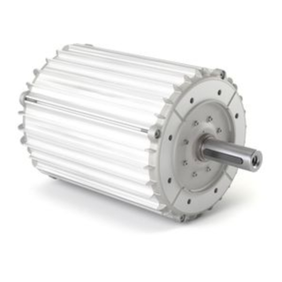
- Page 10 AZ motors are designed in four lamination diameters of stator: 84 mm (AZ 84), 108 mm (AZ 108), 150 mm (AZ 150) and 220 mm (AZ 220). They are made in degree of protection IP54 (closed housing). The motors are equipped with connecting cables and can be easily connected with motor controllers.
- Page 11 AZ motor Edition 4 2.3. Main motor parts: 2.3.1. Parts of motor AZ 84 Picture 3. Main motor parts – AZ 84 Instructions for bearings replacement...
- Page 12 AZ motor Edition 4 Table 6. Main motor parts – motor AZ 84 Number Component part Stator support Stator Housing O – ring (in the bearing seat of the Housing– pos. 3) Rotor (with magnets) Shaft Bearing, front Bearing, rear Wave spring washer Distance ring Bearing fixation washer...
- Page 13 AZ motor Edition 4 2.3.2. Parts of motors AZ 108, AZ 150, AZ 220 Instructions for bearings replacement...
- Page 14 AZ motor Edition 4 Picture 4: Main motor parts – AZ 108, AZ 150, AZ 220 Instructions for bearings replacement...
- Page 15 AZ motor Edition 4 Table 7. Main motor parts – AZ 108, AZ 150, AZ 220 Number Component part Stator support Stator Housing Flange Rotor (with magnets) Shaft Bearing, front Bearing, rear Wave spring washer Shim washer Retaining ring Press ring Screw O –...
-
Page 16: Safety Instructions And Warnings
AZ motor Edition 4 3. SAFETY INSTRUCTIONS AND WARNINGS THE OPERATING AND INSTALLATION INSTRUCTIONS MUST BE READ BEFORE THE INSTALLATION OF THE MOTOR, IT'S USAGE AND IT'S MAINTENANCE! INSTRUCTIONS FOR BEARINGS REPLACEMNET MUST BE READ BEFORE ANY KIND OF MOTOR MAINTENANCE! RISK OF ELECTRIC SHOCK. - Page 17 AZ motor Edition 4 4. SERVICING OF THE MOTOR FOR BEARINGS REPLACEMENT Replacement of the motor bearings is an example of service intervention. Any service intervention should be performed by a qualified person. Disturbing noise from fan motor! Check by spinning the wheel by hand and listen for noise from the bearings. Establish the replacement of bearings if noise from bearings is detected.
- Page 18 AZ motor Edition 4 Step 1: Removing the fan frame with motor Remove the fan frame with motor from AHU. Motor controller must be disconnected from mains. Step 2: Removing the wheel Remove the inlets, fan wheel screw and wheel from motor shaft (Inter dismantle front profile).
- Page 19 AZ motor Edition 4 Step 3: Disconnecting motor cable from motor controller You will need a TORX T20 screwdriver (a) and a small flat screwdriver (g) for this step Open the cover of motor controller and disconnect the motor cable from motor controller. Step 4: Positioning the motor in vertical direction RISK OF INJURY.
- Page 20 AZ motor Edition 4 Step 5: Fixing the motor shaft In this step you must fix motor shaft so that it cannot move axially. Avoid forces in axial or radial direction that are pulling the shaft out or pressing the shaft in. You can damage wave spring washer. For fixing the shaft you can use e.g.
- Page 21 AZ motor Edition 4 17 torx T20 PICTURE A: PICTURE B: Fix motor back on frame that next steps will be easier to perform. Gently tighten motor fixation bolts – you do not need to tighten with high torque – PICTURE C. Instructions for bearings replacement...
- Page 22 Step 7: Removing the motor cover You will need a TORX T20 screwdriver (a) or TORX T30 screwdriver (b) for this step. MOTORS AZ 108, AZ 150, AZ 220 Unscrew two M4 screws (pos. 18) and remove the cover (pos. 17). Use TORX T20 screwdriver (a).
- Page 23 Edition 4 18 (torx T20) 15 (torx T30) MOTORS AZ 108, AZ 150, AZ 220 MOTOR AZ 84 Step 8: Removing rear bearing fixation elements and preload elements You will need a TORX T20 screwdriver or tool (a) or TORX T30 screwdriver or tool (b), retaining ring pliers (c) and heavy duty pliers (d) for this step.
- Page 24 (pos. 10) and wave spring washer (pos. 9). See picture B for additional information. Removed press ring will not be used again on motors 748.3.xxx (motor size AZ 150) and motors 749.3.xxx (motor size AZ 220). It will be changed with new one according to table 4 at page 8 of these instructions.
- Page 25 (b) for this step RISK OF DAMAGE IF WASHERS FALL INSIDE. Every bonding screw on motors AZ 108, AZ 150, AZ 220 has a washer under the head of the screw. Pay attention to these washers and make sure that they do not fall inside of the motor. If the washer falls inside and you forget to take it out then it is possible that motor will damage when you power it on.
- Page 26 For motor sizes AZ 84 you will need three M6 eye bolts (f) for this step. For motor sizes AZ 108 and AZ 150 you will need two M8 eye bolts (f) for this step. For motor sizes AZ 220 you will need two eye bolts with thread M14x1,5 for this step.
- Page 27 Disassemble the stator support with stator (pos. 1) from the rest of the motor. For this purpose use designed threaded holes in stator support. On motors AZ 108, AZ 150 in AZ 220 stator support has threaded holes in two of four holes (holes for bonding screws). In these two threads eye bolts can be fitted and by these two eye bolts we can pull up the stator support with stator.
- Page 28 AZ motor Edition 4 PICTURE B: PICTURE C: MOTORS AZ 108, AZ 150, AZ 220 MOTOR AZ 84 Step 11: Removing the rear bearing If the rear bearing cannot be removed from stator support by hands, you can turn around stator support with stator and push it through the hole in the stator support.
- Page 29 AZ motor Edition 4 Disassemble rear bearing (pos. 8) from the stator support. MOTORS AZ 108, AZ 150, AZ 220 MOTOR AZ 84 Step 12: Removing the fixation of the motor shaft Be careful not to damage the shaft. Avoid forces in axial or radial direction that are pulling the shaft out of the motor.
- Page 30 Be careful not to damage the motor shaft. You can protect motor shaft with cotton cloth or soft metal or plastic. Remove parallel key (pos.13 on AZ 84 and pos. 16 on AZ 108, AZ 150, AZ 220) from motor shaft (pos. 6).
- Page 31 AZ motor Edition 4 MOTORS AZ 108, AZ 150, AZ 220 MOTOR AZ 84 Step 15: Removing the front bearing You will need 2 or 3 handed puller (i) for this step. We recommend using the puller from KUKKO manufacturer (www.kukko.com) with small pulling arms.
- Page 32 AZ motor Edition 4 MOTORS AZ 108, AZ 150, AZ 220 MOTOR AZ 84 Step 16: Installing the new front bearing You will need inductive heater (j) or special tools for front bearing installation (k) and new bearing for this step. We recommend using bearing fitting tool kit TMFT 36 from SKF manufacturer (www.skf.com).
- Page 33 AZ motor Edition 4 Bearing must not be heated over 110°C because higher temperature influence bearing grease which can lead to shorter bearing life time. Ensure that the bearing is installed up to the level on the shaft (bearing seat). Otherwise the distances between the components will not be appropriate.
- Page 34 Apply only a thin layer of assembly paste. Make sure that O-ring is in correct position in bearing seat groove. Place rotor with shaft into flange slowly to the end position. MOTORS AZ 108, AZ 150, AZ 220 MOTOR AZ 84 Instructions for bearings replacement...
- Page 35 Install parallel key (pos.13 on AZ 84 and pos. 16 on AZ 108, AZ 150, AZ 220) into motor shaft (pos. 6). Ensure that parallel key is installed to the end position.
- Page 36 Only for motors AZ 108, AZ, 150 and AZ 220. Motor AZ 84 do not need centering tube. Insert centering tube on the rotor shaft slowly to the end position. MOTORS AZ 108, AZ 150, AZ 220 Instructions for bearings replacement...
- Page 37 When inserting hold the stator only by the eye bolts and not by the stator. For heavier motors (motor type AZ 150 and AZ 220) please use lift because you will not be able to insert stator support with stator and housing slowly due to strong magnetic forces which will pull the rotor and stator suddenly together.
- Page 38 (b) and torque wrench (m) for this step. RISK OF DAMAGE IF WASHERS FALL INSIDE. Every bonding screw of motors AZ 108, AZ 150 and AZ 220 has a washer under the head of the screw. Pay attention to these washers and make sure that they do not fall inside of the motor.
- Page 39 4 bonding screws (pos. 19 for motors AZ 108, AZ 150 and AZ 220 or pos. 16 for motors AZ 84). Under the screw head the washer (pos. 20) has to be mounted (for motors AZ 108, AZ 150, AZ 220). Screw the bonding screws with sufficient tightening torque by using torque wrench (m).
- Page 40 9. The bearing seat is designed to mount the rear bearing manually. If manual rear bearing installation is not possible, use e.g. adjusted press ring and M6 screw (motors AZ 84, AZ 150 and AZ 220) or M4 screw (motor AZ 108) and slowly screw the screw into thread in the shaft to get the right position of bearing.
- Page 41 You must first lubricate bearing seat in the stator support with assembly paste. Apply only a thin layer of assembly paste. Install the new rear bearing. PICTURE A: MOTORS AZ 108, AZ 150, AZ 220 MOTOR AZ 84 PICTURE B:...
- Page 42 M6 screw head (b), torque wrench (m), heavy duty pliers (d) and retaining ring pliers (c) for this step. Table 10: Rear bearing fixation elements and preload elements on motors AZ 108 AZ 150, AZ 220 AZ 84 Press ring (pos. 12) Press ring (pos. 12) Bearing fixation washer (pos.11)
- Page 43 8 while on motors 748.3.xxx (motor size AZ 150) and 749.3.xxx (motor size AZ 220) install the new press ring (pos. 12) from table 4 on page 8 and screw the M4 or M6 screw (pos. 13) by using torque wrench. Tightening torque of screw M4 is 5 Nm and for M6 is 6 Nm.
- Page 44 Edition 4 Step 25: Installing the grounding brush (only motors 748.3.xxx – motor size AZ 150 and 749.3.xxx – motor size AZ 220) You will need a rubber hammer (r) for this step. Only the rubber hammer is allowed to be used. If you use hard hammer (steel, plastic) the hits can damage motor bearings and other parts and motor life time can be shorter.
- Page 45 Cut the hole into rubber seal of motor cover. It has to be approximately on the middle of motor cover. Hole diameter for motors 748.3.xxx (motor AZ 150) is approximately 50 mm and for motors 749.3.xxx (motor AZ 220) approximately 60 mm. Remove the inner seal part.
- Page 46 15 (torx T30) 18 (torx T20) MOTORS AZ 108, AZ 150, AZ 220 MOTOR AZ 84 Step 27: Removing the fixation of the motor shaft Be careful not to damage the shaft.
- Page 47 AZ motor Edition 4 Step 28: Installing the terminal box and cable connection You will need a TORX T20 screwdriver (a), a small flat screwdriver (g), wrench 19 mm (t) and torque wrench (m) for this step. Be careful not to damage motor wires, connector and connecting cable.
- Page 48 AZ motor Edition 4 17 torx T20 PICTURE A: PICTURE B: PICTURE C: Instructions for bearings replacement...
- Page 49 Axial force for fan assembly must not exceed permissible force defined in table 11. Table 11. Permissible force for wheel installation Max. force for Motor type fan assembly [N] 746.3.xxx (AZ 84) 747.3.xxx (AZ 108) 748.3.xxx (AZ 150) 749.3.xxx (AZ 220) Instructions for bearings replacement...
- Page 50 AZ motor Edition 4 Mount fan wheel on motor shaft with very low force. There is no need that wheel is mounted to the end position, just position fan wheel on shaft. Install the tool for fan wheel installation (s) into shaft threaded hole. With screwing the nut of tool for fan wheel installation push the fan wheel to the end position.
Need help?
Do you have a question about the AZ 150 and is the answer not in the manual?
Questions and answers