
Summary of Contents for Boltek EFM-100C
- Page 1 BOLTEK CORPORATION Lightning Detection GSM-1 Text Message Notification for EFM-100C Electric Field Monitor User Guide SEE DISCLAIMER ON REVERSE...
- Page 2 Neither Boltek Corporation nor its affiliates shall be liable to the purchaser of this product or third parties for damages, losses, costs, or expenses incurred by purchaser or third parties as a result of use, misuse, accident, or abuse.
- Page 3 FCC Compliance Statement For United States Users This equipment is tested and found to comply with the limits for a Class B digital device, pursuant to Part 15 of the FCC Rules. These limits are designed to provide reasonable protection against harmful interference in a residential installation.
-
Page 4: Table Of Contents
Table of Contents Introduction ..................1 Installing SIM Card ................2 Setup Instructions ................3 Dialer Configuration ................4 Adding Numbers ................. 4 Alert Messages ..................5 Specifications ..................6 GSM-1 Hardware Specifications ............6... -
Page 5: Introduction
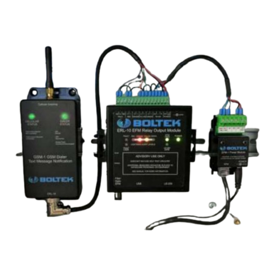
C H A P T E R S E T U P Chapter Introduction he GSM-1 Text Message Dialer provides automatic text message notification as lightning activity approaches. Your GSM-1 package should contain: 1 GSM Cellular Dialer (with cellular antenna) 1 ERL-10 Programmable Output Relay Module 1 EPM-1 Power Module or EFA-21 Power/Data Module 1 AC wall adapter,... -
Page 6: Installing Sim Card
C H A P T E R S E T U P Installing SIM Card 1) Detach GSM-1 from the DIN Rail by pushing up then pull top towards you then pull off the rail. 2) Remove the four screws on the back of the GSM-1 using No.1 Philips screwdriver 3) Insert SIM card with contacts facing down and angled corner to the top. -
Page 7: Setup Instructions
6) After the ERL-10 is powered up, the USB drivers should automatically install if there is an active internet connection on the computer. If there is no internet connection, the USB driver install program can be found on the Boltek USB Flash Drive in the ERL-10 folder. -
Page 8: Dialer Configuration
Chapter C O N F I G U R A T I O N Dialer Configuration Adding Numbers All of the numbers can be stored by sending text message commands to the GSM-1 dialer. The commands are not case sensitive, so any case can be used when sending commands. In order to add text numbers, at least one Master number needs to be setup first before adding other Master<space>number. -
Page 9: Alert Messages
C O N F I G U R A T I O N Alert Messages The messages listed in the table below have all ready been pre-programmed into the dialer: Status Message Modify Command All Clear ALL CLEAR CUSTOMCL Fault Clear EFM FAULT CLEAR CUSTOMDL Fault Active... -
Page 10: Specifications
Notes Appendix Specifications GSM-1 Specifications Power Supply Voltage: 11.8-18 VDC, 0.8 Amp Idle Current: 10-25mA Current Max: 160mA SIM Size: Micro Antenna: U.FL Max Phone Numbers: GSM-1 Dimensions: " x 2 " x 1 " (135 x 60 x 30 mm) GSM-1 Weight: 0.2 lbs (100 gm) Enclosure Dimensions:... - Page 11 Notes...
Need help?
Do you have a question about the EFM-100C and is the answer not in the manual?
Questions and answers