Table of Contents
Advertisement
Advertisement
Table of Contents

Related Manuals for Laskomex MVC-8151


Summary of Contents for Laskomex MVC-8151
- Page 1 COLOR MONITOR MVC-8151 for Laskomex digital video door entry systems...
-
Page 2: Table Of Contents
Color monitor MVC-8151 Table of Contents 1. Terms of use and operation ..............2. Purpose and functions of the monitor ............3. Using the monitor ................Conversation ..................Switching to simplex mode ..............Control of the electric strike and drive of the entrance gate ..... -
Page 3: Terms Of Use And Operation
(Figure 6). 2. Purpose and functions of the monitor MVC-8151 is a color monitor dedicated to Laskomex digital video door entry systems. The monitor is a hands-free device that allows you to talk and watch the caller on the screen. The monitor is equipped with illuminated fields that act as buttons. Touching any of the fields di-... -
Page 4: Using The Monitor
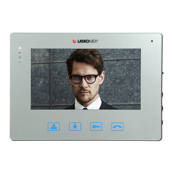
BRIGHTNESS COLOT CONVERSATION PREVIEW VOLUME (conversation) CONTROL KEY(LOCK) Figure 1. Monitor MVC-8151 3. Using the monitor Conversation An attempt to establish a connection with the monitor is signaled by the bell, at the same time the caller’s image will appear on the screen. To make a call, press the CONVERSATION button during the call or within 30 seconds after the call. The talk time is limited and is 120 seconds by default. 10 seconds before the end of this time, short beeps will appear in the loudspeaker indicating that the end of the call is approaching. -
Page 5: Control Of The Electric Strike And Drive Of The Entrance Gate
Color monitor MVC-8151 Control of the electric strike and drive of the entrance gate The LOCK and CONTROL buttons are active only during the call (conversation). Pressing the LOCK button will release the entrance lock (electric strike or electromagnetic lock), which is indicated by the LED2 blinking. -
Page 6: Using The Door Phone
Color monitor MVC-8151 4. Using the door phone Using the code lock function • Enter the apartment number and confirm with the KEY button. • When at the display the ---- message appears, enter the four-digit lock code. • If the entered code is correct, the entry lock will be released. • If the entered code is incorrect, Err message will be displayed. • The use of a code at the subordinate entrance is signaled in the receiver. Providing cor- rect code signals three short beeps, an incorrect – two long ones. • The code lock function can be blocked by the installer. At the main entrance we use the same code as at the subordinate entry. -
Page 7: The „Quick Entry" Function
Color monitor MVC-8151 Figure 2. Using electronic keys: a) iButton touch keys, b) RFID proximity keys The „quick entry” function The function is available in the door entry system with the main entrance and the subordi- nate entrance (entrances). The visitor must first call the chosen apartment by selecting its number in the panel at the main entrance, then he must repeat this operation at the entrance to the staircase. If the „qu-... -
Page 8: Change Of Tone, Call Volume And Number Of Rings
Color monitor MVC-8151 call volume call tone number of rings Figure 3. User menu User menu allows to: • change the call tone, • change the call volume, • set the number of rings, • change the code of the code lock. • register electronic keys. To make changes a tenant must activate User menu. The help of the person in the apartment is needed for this. To activate the User menu, perform the following steps:... -
Page 9: Code Change Of The Code Lock
Color monitor MVC-8151 Code change of the code lock This option can be blocked by installer. • Activate User menu. • Select [0] button. There will appear four horizontal lines. • Enter the current installer code. This step can be omitted if the installer decides so. • For a moment [NEU] and [CODE] messages and then four horizontal lines will appear. -
Page 10: Installation And Activation Of The Monitor
Color monitor MVC-8151 5. Installation and activation of the monitor Execution of electrical installation Detailed recommendations regarding the electrical installation of the video door entry sys- tem can be found in the operating instructions of the CD-2502 or CD-3100 digital door pho- nes. -
Page 11: Connecting An Additional Camera Or Commax Panel
Color monitor MVC-8151 Connecting an additional camera or COMMAX panel To the monitor can be connected an additional camera or COMMAX video door entry pa- nel. The CN CAM2 connector is used for this purpose. In the case of an external panel, connect the wires in accordance with the description of the plug. The panel allows you to call the monitor, conduct a conversation, pressing the electric stri- ke’s button in the monitor will activate the relay in the panel, which can control the electric strike. As an additional camera a standard camera with a COMPOSITE VIDEO output can be used. It can be a disc camera, a dome camera, a camera in the form of a viewfinder etc. -
Page 12: Setting The Monitor Number
Color monitor MVC-8151 Setting the monitor number To program a number you should do in order the following operations: • Press the PROG button three times. The monitor goes into programming mode, which is signaled by a short simultaneous flashing of LED1 and LED2 signaling diodes. • Setting the number of hundreds. Press the CONVERSATION button as many times as hundreds has the programmed number (0, 1 or 2). Each press is signaled by blinking LED2. End the operation with the LOCK button, which will be confirmed by a long flash... - Page 13 Color monitor MVC-8151 CN-CAM2 CN-BP PORT black black white white blue blue CN-CD CN-PWR CAM1+ black CAM1- black white blue CN-BELL BELL black Figure 5. Description of the monitor connection plugs CN_PWR PROG connector* JP1 – C+, C- line con guration (CAM1+, CAM1-) BNC –...
-
Page 14: Adjusting The Monitor
Color monitor MVC-8151 • UTP+TERMINATOR – set the jumper in this position if the video signal is sent symme- trically with the UTP cable and the monitor is located at the end of the video bus or is the only line load. In this position the line is loaded with a 100R resistor. -
Page 15: Doorbell Function
Color monitor MVC-8151 ler can check the operation of the video, sound and electric strike. • End the conversation. 8. Doorbell function In the monitor there is a generator which can function as a door bell. The generator is activated with a bell button connected to appropriate terminals in the mo- nitor. -
Page 16: Technical Data And Wiring Diagram
Color monitor MVC-8151 10. Technical data and wiring diagram Power: 15V DC/1A Recommended power supply: KSAS0181500120, SAPC15018EU Screen diagonal: 7” Protection degree: IP30 Operating temperature: (5 – 40) °C Dimensions: 213x152x21 mm - 16 -... - Page 17 Color monitor MVC-8151 MVC-8151 CN_BP CN_CAM2 CN_CD CN-PWR CN_BELL controller* porter door entry panel switchboard COMMAX** button splitter CVR-2 MON1...MON4 to EC-2502 or EC-3100 power supply ~230V Figure 7. Monitor wiring diagram - 17 -...
- Page 18 Color monitor MVC-8151 - 18 -...
- Page 19 Color monitor MVC-8151 - 19 -...
- Page 20 Used equipment cannot be placed with other wastes from households. Product user is obliged to give it to the firm which collects used electronic or electric equipment such as local collection points, shops, places appointed by the manufacturer or commune waste collection units. List of collecting units of used Laskomex equipment is available on www.laskomex.com.pl or tel. 42 671 88 68. Product packing should be removed according to environment protection regulations. Remember!
Need help?
Do you have a question about the MVC-8151 and is the answer not in the manual?
Questions and answers